
TM-9-4935-294-15/2
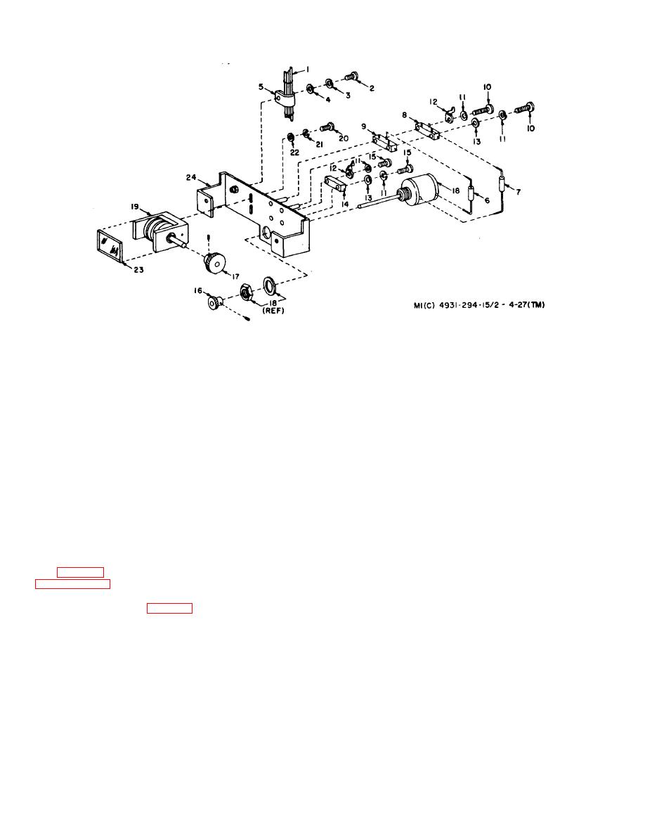
1-Harness-792308-1
12-Lug, solder-7923256-1
2-Screw, machine, pan hd, no. 6-32, 1/2 in. lg, UNC-
13-Washer, flat, round, steel, cd-MS27183-2
2A-MS-35206-230
14-Resistor,variable (R1505)-7923072-3
3-Washer, lock, split, helical, no. 6-MS35338-41
15-Screw, machine, pan hd, no. 2-56, 5/8 in. Ig,
4-Washer, fiat-MS271834
UNC2A-MS-35206-208
5-Clamp, loop-plastic, wire support-MS25281-5
16-Gear, helical-7923058-14
6-Resistor, fixed (R16506)-RH2-OX1501F
17-Gear, helical-7923058-6
7-Resistor, fixed (R1508)-RH2-OX5621F
18-Resistor, variable, 10-turn (R-1502)-7923070
8-Resistor,variable (R1601)-7923072-4
19-Counter assy-7923057
9-Resistor. variable (R1503)-7923072-1
20-Screw, machine, pan hd, no. 4-40, 3/8 in. Ig,
10-Screw machine, pan hd, no. 2-56, 7/8 in. Ig, UNC-
UNC-2A-MS-35206215
2A--MS-35206210
21-Washer, lock, split, helical, no. 2--MS35338-40
11-Washer, lock, split, helical, no.
22-Washer, flat, round, steel, cd-MS27183-3
2-
MS35338-39
23--Window-7923060
24-Bracket assy-7923041-1
Figure 4-27. Counter Assembly 7923056-6, Exploded View.
(c) Two screws (8) from waveguide support side
(d) Two screws (9) from flange engagement.
(10, fig. 4-12). Follow applicable procedures outlined in
(8) Remove four screws (10) from tube support
paragraph 4-17 e (1).
brackets.
(7) Remove the following attaching hardware from
(9) Slide BWO tube (5) and waveguide assembly
waveguide support (37, fig. 4-25) and flange of
(11) from rf head chassis (39).
waveguide assembly (11) in indicated order:
(a) Four hex nuts (6)
(b) Four washers (7)
4-42
