
TB 11-6625-2974-30
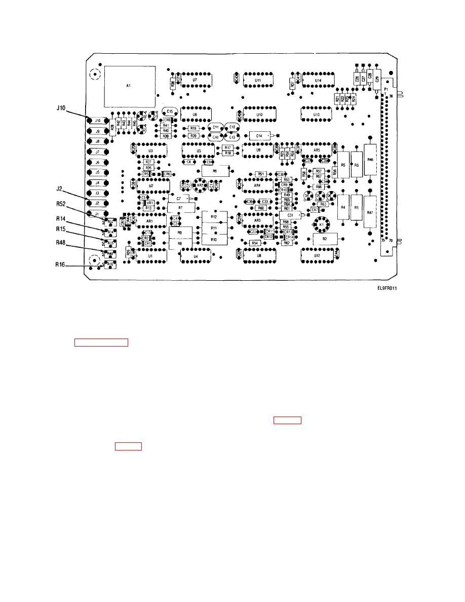
Figure 4-7. DVM Logic Module A5A1 Parts Locations.
(8) Observe METER. Display should be +30..
(3) Remove jumper wire and connect external
(9) If METER display in steps (4) and (8) was -
power supply (set for + 30.. 0.05 V) to
00.and +30.00, the performance standard is met.
EXTERNAL INPUT red (+) and gray (-) jacks.
Go to paragraph 4-5 for the next performance
(4) Adjust A5A1-R14 (fig.4-7) to obtain a display of +
check. If the standard is not met, there are two
30.
on METER.
adjustment procedures available. If the -00.0
(5) Repeat steps 1 thru 4 until both standards are
display was within + 0. V and the + 30.00
met without further adjustment.
display was within 3 V, go to subparagraph d
e. DVM Logic Major Adjustment.
(below) for the minor adjustment procedure. If
(1) Disconnect external power supply. Connect a
the display was outside the ranges listed above,
jumper wire between the front panel EXTERNAL
go to subparagraph e (below) for the major
INPUT jacks.
adjustment.
(2) Locate DVM logic module A5A1 in card cage
d.
DVM Logic Minor Adjustment.
(1) Connect jumper wire between the front panel
(3) Connect DVM to A5Al-J2 (+) (fig.4-7)
and
EXTERNAL INPUT jacks.
A5Al-J1O (-).
(2) Adjust A5AI-R16 (fig. 4-7) to obtain a display of -
(4) Adjust A5A1-R48 to obtain a reading of 0. 0.02
00.on METER.
V on DVM.
4-9

