
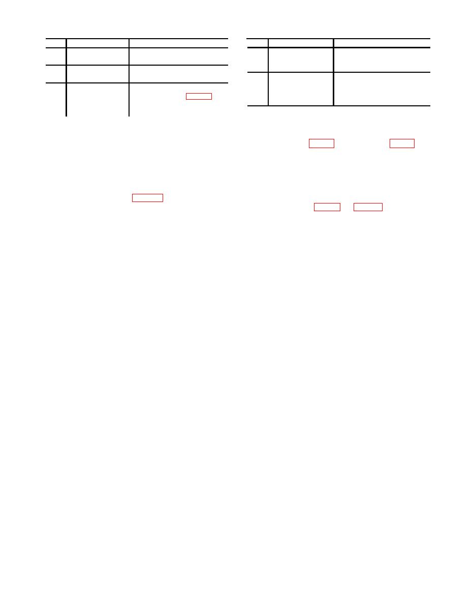
Table 3. Accessories Required
Item
Common name
Description and part number
Item
Description and part number
Common name
conductor cable Double pole,
B1
AWG
Lead
20 wire cut in 12 inch
double throw switch 18 connec-
lengths
tion terminal board.
B2
Must measure from zero to 60 sec-
Stopwatch
B4
Test cable No. 2
Test cable No. 2 consists of 30 con-
ends in seconds
ductor cable 4 feet long Plug Ben-
B3
Assemble special test cable No. 1 in
Test cable No. 1
dix PT06E-18-32S (RS) 30 con-
accordance with figure 1. Cable
nection terminal board.
consists of plug Bendix
PT06A-14-15S (SR) four feet 10
16 required.
SECTION III. PRELIMINARY OPERATIONS
WARNING
lined in this section are preparatory to the calibration
HIGH VOLTAGE is used during the perform-
process. Personnel should become familiar with the entire
bulletin before beginning the calibration.
ance of this calibration. DEATH ON CON-
TACT may result if personnel fail to observe
b. Items of equipment used in this procedure are
precautions.
referenced with the text by common name and item iden-
tification number as listed in tables 2 and 3. For the iden-
tification of equipment referenced by item numbers

