
b.
Adjustments. No adjustments can be made.
manometer (A2) to atmospheric pressure.
(6) Disconnect the test equipment.
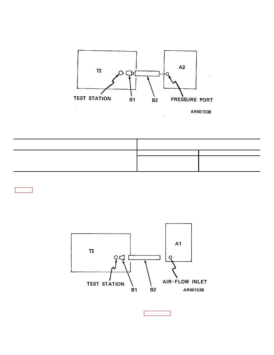
Figure 3. PRESSURE gage performance check, equipment setup.
Table 4. Pressure Gage Performance Limits
Scale major Division Indications
Acceptable Manometer Indications
(inches of water)
Min.
Max.
1.06
0.94
1
2.06
1.94
2
3.06
2.94
3
(3) Repeat (2) above for " 10" on the AIR
9. AIR FLOW Gage. a Performance Check.
FLOW gage. Flowmeter (Al) must indicate between
(1) Connect the test equipment as shown in
32.6 and 37.4.
(4) Release the TEST switch.
(2) Adjust AIR FLOW VALVE to obtain a
(5) Disconnect the test equipment.
reading of "4" on the AIR FLOW gage. Flowmeter (Al)
b. Adjustments. No adjustments can be made.
must indicate between 82.6 and 87.4.
Figure 4. AIR FLOW gage performance check, equipment setup.
the TI does not indicate within the limits specified in
10. Final Procedure. a. Deenergize and disconnect
all equipment.
(Unserviceable or Limited Use) tag.
b. In accordance with TM 38-750, annotate and
affix DA Label 80 (US Army Calibration System). When
4

