
TB 9-4920-360-24
8. Temperature
a. Performance Check
(1) Connect multimeter to SIGNAL OUTPUT (J2) pin E (+) and pin D (-).
(2) Place probe end of thermometer adjacent to terminals of J2. Wait 10 minutes
for thermometer to stabilize.
NOTE
Constantly check thermometer temperature values to insure
proper millivolt values.
(3) Set TEMP OUTPUT control for 400 C plus value in degrees C as indicated on
thermometer. If multimeter indication is not between 16.14 and 16.65 mV dc, perform
b (1) below.
(4) Set TEMP OUTPUT control for 800 C plus value in degrees C as indicated on
thermometer. If multimeter indication is not between 33.031 and 33.523 mV dc, perform b
(2) and (3) below.
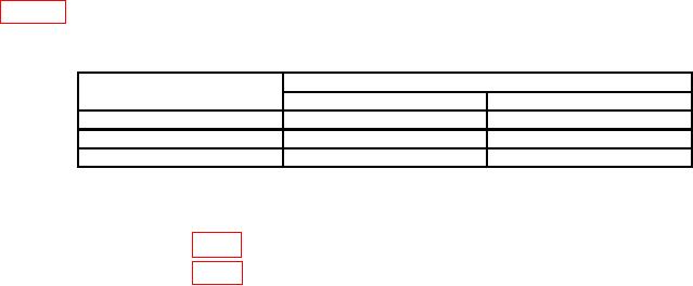
(5) Repeat technique of (4) above at TEMP OUTPUT control settings listed in
table 3. Multimeter indications will be within limits specified.
Table 3. Temperature Check
TEMP OUTPUT
Multimeter indications (mV dc)
control settings
Min
Max
500
20.385
20.896
600
24.646
25.157
700
28.877
29.380
b. Adjustments
(1) Adjust R40 (fig. 1) for 16.400 mV dc indication on multimeter (R).
(2) Adjust R42 (fig. 1) for 33.257 mV dc indication on multimeter (R).
(3) Repeat a (3) and (4) and b (1) and (2) above, as necessary, for best in-tolerance
compromise.

