
TB 9-4920-451-24
9. Capacitance Measurement Calibration
a. Performance Check
(1) Set MODE SELECT switch to MEAS EXT position.
(2) Set RANGE switch to LO position.
(3) Connect shorting plug (p/o TI) to TO PROBES LOZ COMP (fig 1).
(4) Connect variable capacitor to TI, G to TO PROBES LOZ and 115 to TO
PROBES HIZ.
(5) Adjust variable capacitor to 40 pF. TI display will indicate between 39.8 and
40.2 pF.
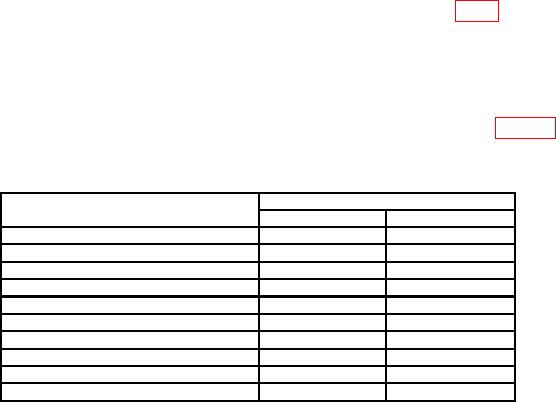
(6) Repeat technique of (5) above for settings and indications listed in table 3.
b. Adjustments. No adjustments can be made.
Table 3. Capacitance
Test instrument indications (pF)
Capacitance standard settings
(pF)
Min
Max
60
59.7
60.3
80
79.6
80.4
100
99.5
100.5
180
179.1
180.9
300
298.5
301.5
400
398
402
600
597
603
800
796
804
10001
995
1005
20001, 2
1990
2010
1Set
RANGE switch to HI for 1000 and 2000 pF.
2Connect
capacitance standard 0.002 G to HIZ and remaining banana jack to LOZ for 2000 pF.
10. Capacitance Substitution Calibration
a. Performance Check
(1) Configure the precision component analyzer to measure capacitance and connect
to TO IND LOZ and TO IND HIZ on TI.
(2) Connect shorting plug (p/o TI) to TO IND LOZ COMP.
(3) Energize precision component analyzer and allow sufficient warm-up time.
(4) Set MODE SELECT switch to MEAS INT position.
(5) Set T/U COMP switch to T/U and RANGE switch to LO position.
(6) Set TANK UNIT SIMULATOR X1000 pF and X100 pF switches to 0.
(7) Adjust TANK UNIT SIMULATOR SET control for a 40 pF reading on digital
display (push down on control for coarse tuning and let up for fine tuning).

