
TB 9-4920-454-24
b. Adjustments
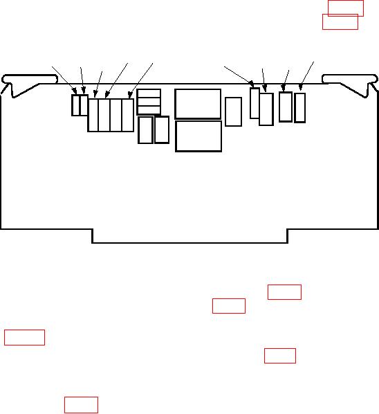
(1) Connect frequency counter between TP3 (+) and TP2 (-) (fig. 3). Frequency
counter will indicate between 97.0 and 103.0 s; if not, adjust R26 (fig. 3) for a 100 s
indication on frequency counter (R).
R66
R65
TP1
R59
R26
TP2
TP3
R69
R57
Figure 3. Temperature circuit board.
(2) Connect multimeter between TP1 (+) and TP2 (-) (fig. 3). If multimeter does not
indicate between 7.255 and 7.295 mV dc, adjust R65 (fig. 3) for an indication of 7.275 mV dc.
(3) Adjust calibrator for a dc millivolt output equal to ambient temperature
obtained in table 3, plus .017 mV.
(5) Adjust calibrator for a 55.820 mV dc, less millivolt equivalent to ambient
temperature, output.
(7) Repeat a (1) and a (3) through (8) above, as necessary, to ensure TEMP oC
indicator is in tolerance at both points.
NOTE
Perform paragraph 9 below only if adjustments were made in
8 b above.
9. Calibrator Board
a. Performance Check
(1) Place thermometer adjacent to calibrator OUTPUT terminals. Wait 10 minutes
for thermometer to stabilize and record ambient temperature.

