
TB 9-4931-287-40
8. Output Accuracy
a. Performance Check
(1) Turn MILLIVOLT switch to 0 (zero) and MILLIVOLT control to 0 (zero).
(2) Press and lock GA switch.
(3) Set FUNCTION switch to SC and adjust STD control for null indication on
galvanometer.
NOTE
Repeat (3) above as necessary during remainder of this
procedure to assure stability of TI. Instability is often caused
by internal batteries and/or internal standard cell and should
be corrected before continuing with the calibration.
(4) Turn FUNCTION switch to OUTPUT 1. Null detector will indicate between 0 and 50 V.
(5) Connect equipment as shown in figure 1, connection B.
(6) Set dc voltage divider controls to .1000000.
(7) Set MILLIVOLTS switch to 20 and adjust calibrator for 0.20000 V.
(8) While increasing sensitivity of null detector, readjust output of calibrator to
obtain best null on null detector. Output of calibrator will be between 0.1994 and 0.2006 V.
(9) Repeat technique of (7) and (8) above, using values in tables 3. Calibrator output
will be within limits specified.
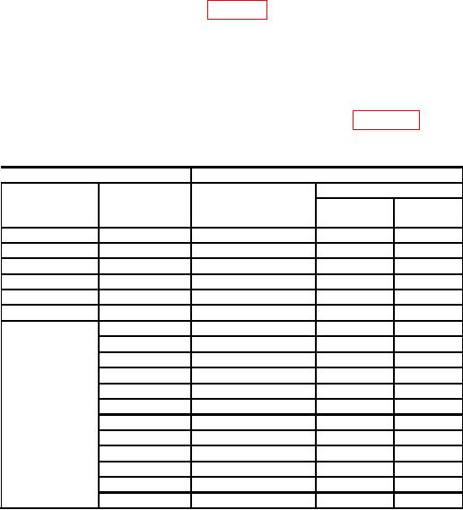
Table 3. Output 1 Accuracy
Test instrument
Calibrator
MILLIVOLT
Final setting (V)
MILLIVOLT
Initial setting (V)
control
switch setting
Min
Max
setting
40
0
0.4
0.3993
0.4007
60
0
0.6
0.5992
0.6008
80
0
0.8
0.7991
0.8009
100
0
1.0
0.9990
1.0010
120
0
1.2
1.1989
1.2011
140
0
1.4
1.3988
1.4012
1601
0
1.6
1.5987
1.6013
2
1.62
1.6187
1.6213
4
1.64
1.6387
1.6413
6
1.66
1.6587
1.6613
8
1.68
1.6787
1.6813
10
1.70
1.6986
1.7014
12
1.72
1.7186
1.7214
14
1.74
1.7386
1.7414
16
1.76
1.7586
1.7614
18
1.78
1.7786
1.7814
20
1.80
1.7986
1.8014
22
1.82
1.8186
1.8214
Do not change MILLIVOLT switch setting.
1

