
TB 9-4931-488-35
(13) Position controls as listed in (a) through (i) below.
(a) AM X10% pushbutton pressed.
(b) AM SWITCH to AC.
(c) FM switch to OFF.
(d) RANGE MHz switch to 128-64.
(e) FREQUENCY TUNE control for FREQUENCY MHz display indication of
113 MHz.
(f) AM control fully ccw.
(g) OUTPUT LEVEL 10 dB switch to 0 dBm.
(h) OUTPUT LEVEL 1 dB switch to 0.
(i) OUTPUT LEVEL vernier to CAL.
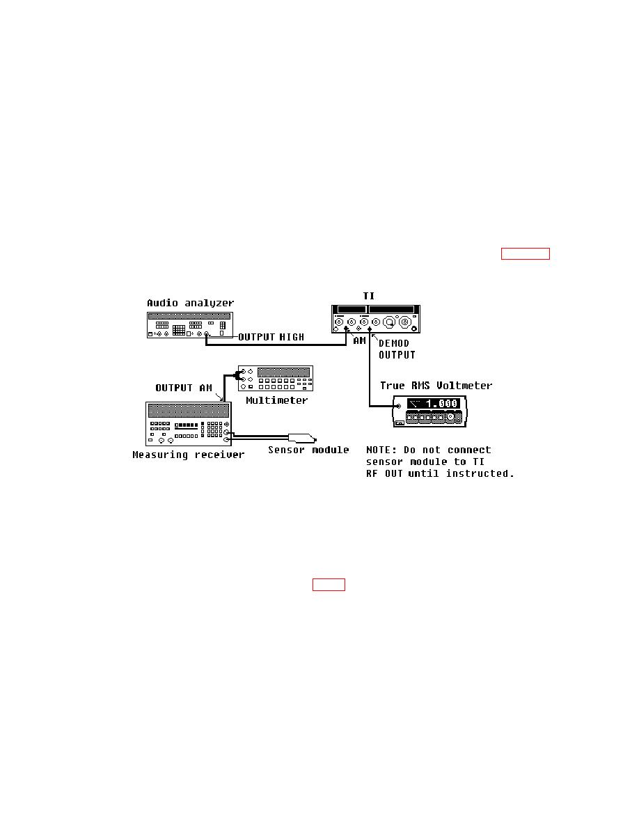
(14) Reduce all outputs to minimum and reconnect equipment as shown in figure 6,
leaving TI RF OUTPUT disconnected.
(15) Press measuring receiver AUTOMATIC OPERATION and MHz (INPUT
FREQ ) keys.
(17) Connect TI RF OUTPUT to measuring receiver sensor module.
(18) Note position of switch A26A8S1 (fig. 2) and set to AC position. If necessary,
turn RF OUTPUT ON.
(19) Adjust audio analyzer controls for a 1 V, 120 Hz output signal.
(20) Adjust AM control for a true RMS voltmeter indication of 1.000 V ac (if necessary
use audio analyzer up/down arrows to fine adjust). Press 6.2 and SPCL keys on measuring
receiver.
33

