
TB 9-4931-491-35
(8) Adjust CENT FREQ controls slowly across entire band and note the minimum
output indication.
(9) Measuring receiver will indicate at least +8.5 dBm across entire band.
b. Adjustments. No adjustments can be made.
13. Attenuator Accuracy
a. Performance Check
(1) Connect measuring receiver power sensor module to TI RF OUT.
(2) Position controls as listed in (a) through (c) below:
(a) MODE switch to CW.
(b) CENT FREQ control to 250 MHz.
(c) OUTPUT control to 0 dBm.
(4) Tune measuring receiver to 250 MHz (.250 GHz) with a 0.000 reference.
(5) Set OUTPUT control to -10 dBm.
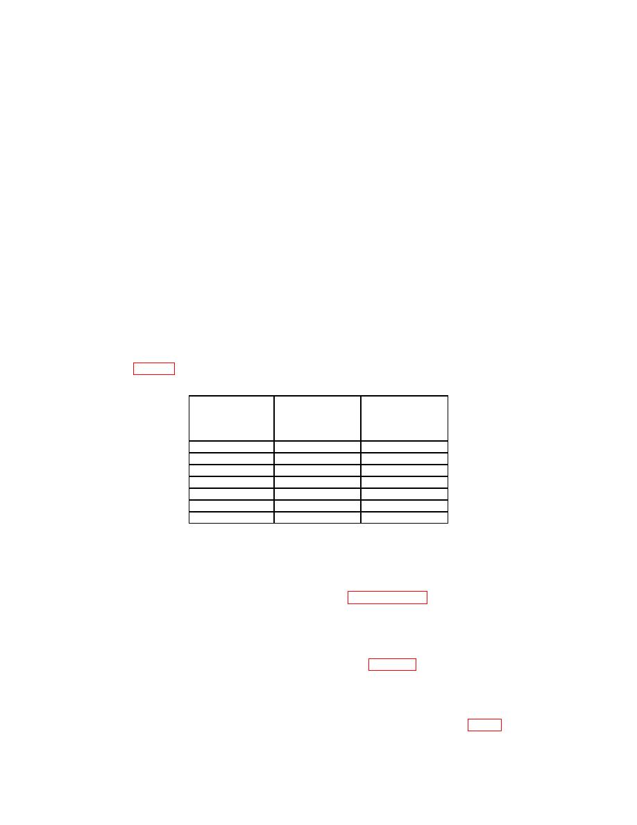
(6) Using standard tuned level measurement techniques, verify the measuring
receiver indicates within minimum and maximum limits for TI OUTPUT control settings
as listed in table 3 below.
Test instrument
OUTPUT
control
Min
Max
(dBm)
-10
-10.5
-9.5
-20
-20.5
-19.5
-30
-30.5
-29.5
-40
-40.5
-39.5
-50
-50.5
-49.5
-60
-60.5
-59.5
-70
-70.5
-69.5
b. Adjustments. No adjustments can be made.
14. Power Supply
NOTE
Do not perform power supply checks (paragraphs 14 through
17) if all other parameters are within tolerance.
NOTE
Remove TI top cover, left side panel, and M2H module cover
before starting performance checks. (See figure 5 for location of
monitoring points and adjustments.)
a. Performance Check
(1) Connect multimeter to pin 6 on power plug and chassis ground (fig. 4).

