
TB 9-4931-534-35
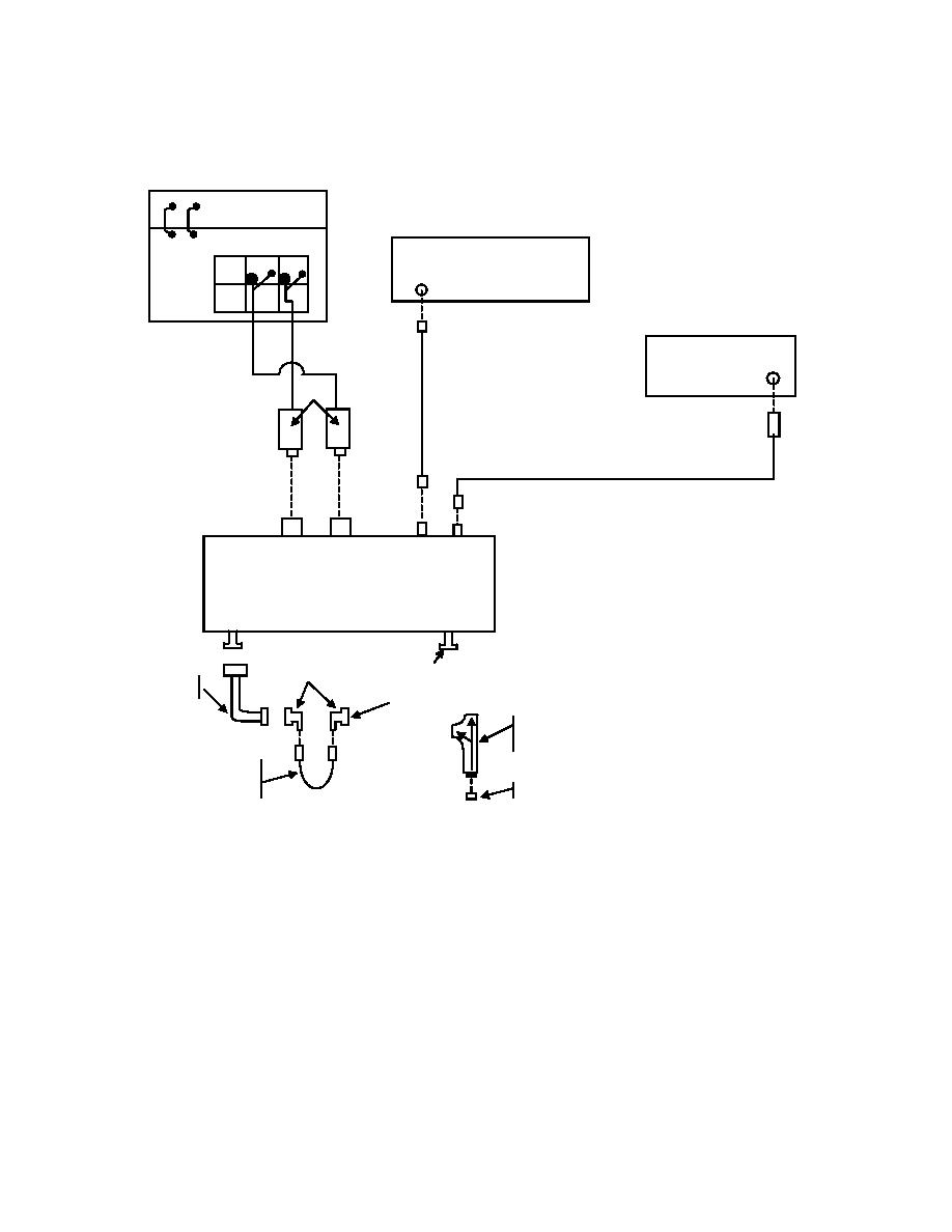
RECEIVER SYSTEM
SIGNAL GENERATOR
CH1 CH2
RF OUT
SYNTHESIZED SIGNAL GENERATOR
RF
OUTPUT
LOW BAND PROBES
REFERENCE
MEASUREMENT
RF
LO
CHANNEL 1
CHANNEL 2
FREQUENCY EXTENSION NO. 14
TEST
SIGNAL PORT
WAVEGUIDE
TO COAXIAL
POINT B2
ADAPTER1
WAVEGUIDE
BEND1
POINT A2
DIRECTIONAL
COUPLER NO. 3
SMA
SEMI-RIGID1
FIXED SHORT3
1Waveguide
to coaxial adapters, 90 degree waveguide bends, and
SMA semi-rigid cable part of frequency extension kit.
2Points
A and B are used in isolator equipment setup only. Point
A is input to waveguide to coaxial adapter and Point B is output
of signal port.
3Maury,
Model K344A fixed short part of microwave standards
kit, 18 to 26.5 GHz.
4Part
of frequency extension kit.
10

