
TB 9-5120-212-24
NOTE
For PD 12003, if indications are not in tolerance, prepare a test
report (correction chart) showing actual values for nominal TI
indications of 5500 and 6000 ft-lbs. Calibration points must be
approached operating crank handle between the 2 o'clock and
4 o'clock positions.
NOTE
The calibration points must be approached in the direction of
increasing torque. If calibration point is passed, reduce torque
and approach calibration point again.
NOTE
On some models, it is necessary to lift pin on indexer ratchet
drive on top of TI to change cw and ccw directions.
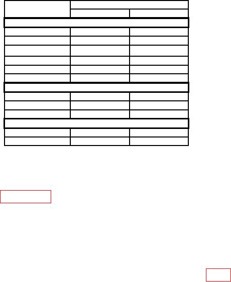
Table 4. Calibration Accuracy
Test instrument
Torque cell indications (ft-lbs)
indications (ft-lbs)
Min
Max
Model PD 1201 (and Models DPT-1200 and DPT-1200R)
(250)
(245)
(255)
300
(400)
276
(392)
324
(408)
500
(600)
476
(588)
524
(612)
750
(800)
726
(784)
774
(816)
1000
(1000)
976
(980)
1024
(1020)
1200
(1200)
1176
(1176)
1224
(1224)
Model PD 2501 (and Models DPT-2500 and DPT-2500R)
1500
1450
(1470)
1550
(1530)
2000
1950
(1960)
2050
(2040)
2500
2450
(2450)
2550
(2550)
Model PD 12003
5500
5335
5665
6000
5820
6180
NOTE
Perform (4) below for ccw calibration only when specifically
requested by user.
(4) Perform paragraph 7 above and select the torque cell for the TI range and
cw torque.
(5) Repeat a (1) through (3) above, except turn crank handle ccw.
(6) Turn TI crank handle cw to obtain a 0 indication.
b. Adjustments
NOTE
Reaction arm must be free to move under retaining screws (fig. 1).
6

