
TB 9-5210-216-24
(3) TI will indicate within 0.001 inch or 0.01 mm of pitch diameter indicated on
thread plug gage.
b. Adjustments. No adjustments can be made.
10. Linearity
a. Performance Check
NOTE
The TI indications obtained in this section will be larger than
the gage block values due to the geometry of the measuring
surface of the spindle and anvil.
(1) Adjust the TI so that a 0.0500 inch gage block can be placed between the
spindle and anvil. If the TI has a range greater than one inch, wring the appropriate
gage blocks to the 0.0500 inch gage block. If the TI is metric, use a 1.00 mm gage block
between the anvil and spindle. If the TI has a range greater than 25 mm, wring the
appropriate gage blocks to the 1.00 mm gage block.
CAUTION
Do not over tighten the TI thimble as the spindle tip or the
gage block may be damaged
(2) Place the gage block(s) between the TI spindle and anvil and carefully adjust the
TI thimble so that a measurement of the gage block(s) can be obtained.
(3) Annotate TI reading to the nearest 0.001 inch or 0.01 mm. This will be the TI
nominal reading.
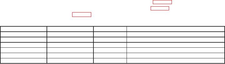
(4) Repeat steps (2) and (3) above for settings listed in table 3 below, except replace
the 0.0500 inch or 1.00 mm gage block with ones indicated in table 3 below. TI will indicate
within specifications listed in table 3 below.
Table 3. Linearity
English (inches)
Metric (mm)
TI reading
Tolerance: inches (mm) from nominal
0.0500
1.00
Nominal
0.195
4.95
0.0010 (0.010)
0.390
9.90
0.0010 (0.010)
0.585
14.85
0.0010 (0.010)
0.780
19.80
0.0010 (0.010)
0.975
24.75
0.0010 (0.010)
b. Adjustments. No adjustments can be made.
11. Final Procedure
a. Deenergize and disconnect all equipment and reinstall protective cover on TI.
b. Annotate and affix DA label/form in accordance with TB 750-25.

