
TB 9-5220-211-40
5. Accessories Required. The accessories required for this calibration are common
usage accessories issued as indicated in paragraph 4 above, and are not listed in this
calibration procedure.
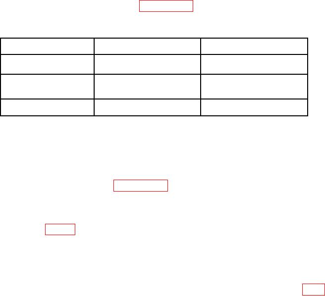
Table 2. Minimum Specifications of Equipment Required
Manufacturer and model
Common name
Minimum use specifications
(part number)
GAGE BLOCK SET
Range: 1.2 to 6.3 in
Grade 1, Class I (7901765)
Accuracy: 0.000012 in
HEIGHT GAGE
Range: 1.2 to 6.3 in
Federal Products Corp.,
Accuracy: 0.00001 in
Electro-Check, Model 230P-121
(7904823)
Accuracy: 0.000050 in
SURFACE PLATE
DoAll Mfg. Co., 18 x 24-in.
(7900123)
CALIBRATION PROCESS
6. Preliminary Instructions
a. The instructions outlined in paragraphs 6 and 7 are preparatory to the calibration
process. Personnel should become familiar with the entire bulletin before beginning the
calibration.
b. Items of equipment used in this procedure are referenced within the text by common
name as listed in table 2.
c. Unless otherwise specified, verify the results of each test and whenever the test
requirement is not met, take corrective action before continuing with the calibration.
7. Equipment Setup. Place TI on surface plate with butt plate up. Set height gage and
two stacks of gage blocks on surface plate. The two stacks of gage blocks must be the same
height as the two rolls of the TI, within the measuring range of the height gage (fig 1).
Allow all equipment to thermally stabilize for at least 12 hours.
NOTE
The approximate height of the gage block buildup can be
determined prior to thermal stabilization by alternately
moving the height gage stylus over the sine plate rolls and the
corresponding gage block buildup. After the items have
thermally stabilized, they must not be handled with the hands.
Use forceps for handling the TI and gage blocks.

