
TB 9-5985-314-35
controls for +6 dBm.
NOTE
Use 15% SEARCH MODE on receiver system.
(14) Connect POINT A to POINT B (fig. 4) and establish a 0.00 dB reference on
receiver system at 2.000 GHz.
(15) Connect TI into figure 4 equipment setup as listed in (a) through (c) below:
(a) INPUT PORT 1 to POINT A.
(b) OUTPUT PORT 2 to POINT B.
(c) OUTPUT PORT 3 to 50 Ω termination.
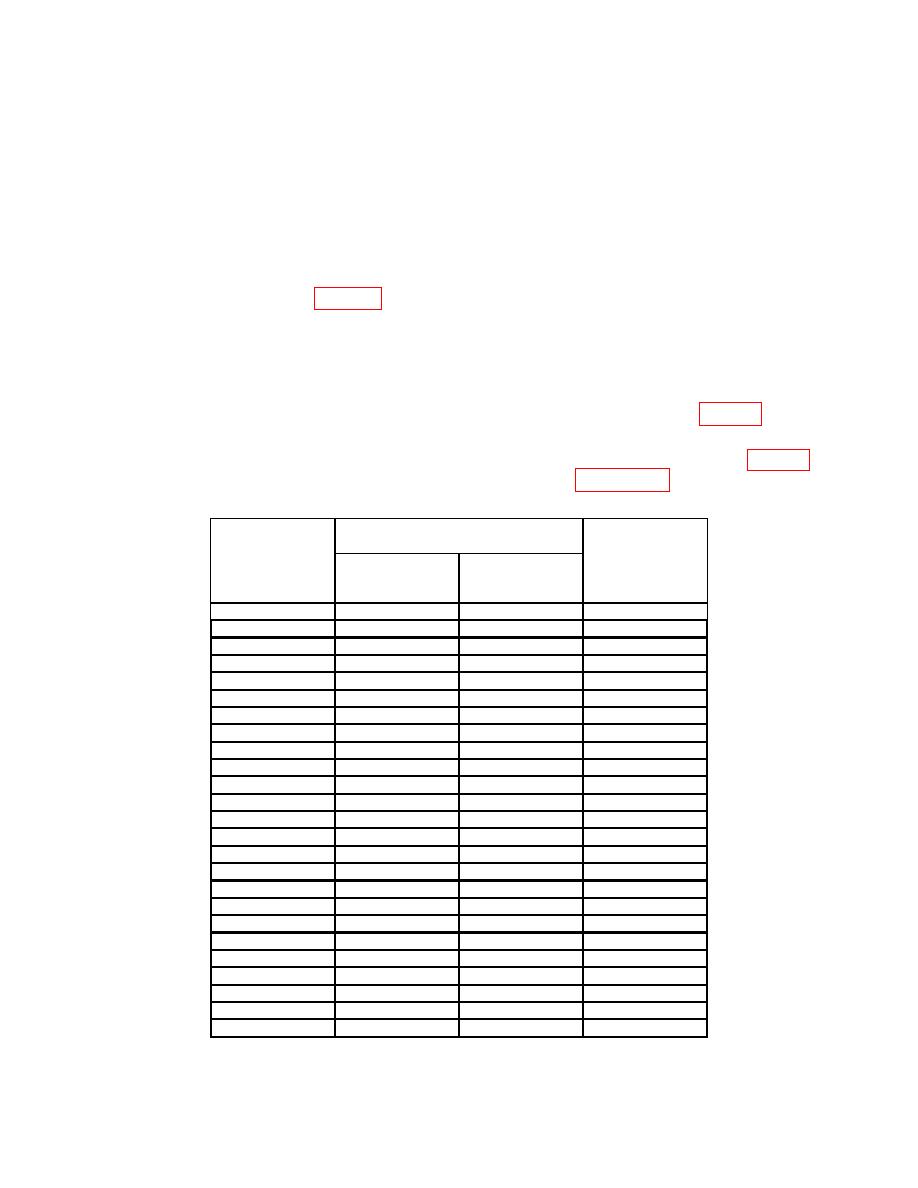
(16) Record receiver system indication in OUTPUT PORT 2 column of table 7.
and record insertion loss for OUTPUT PORT 2 for remaining frequencies listed in table 7.
Insertion loss will be equal to or less than the limits listed in Appendix D.
Receiver system indication
insertion loss
OUTPUT
Test
OUTPUT
OUTPUT
PORT
frequency
PORT 2
PORT 3
TRACKING
(GHz)
(dB)
(dB)
(dB)
2.000
2.500
3.000
3.500
4.000
4.500
5.000
5.500
6.000
6.500
7.000
7.500
8.000
8.500
9.000
9.500
10.000
10.500
11.000
11.500
12.000
12.500
13.000
13.500
14.000
25

