
TB 9-6625-096-50
(3) Record indication of true rms voltmeter.
(4) Turn LOC-GS control of TI fully clockwise.
(5) Record indication of true rms voltmeter.
(6) Subtract indication recorded in (3) above from indication recorded in (5)above
and divide the difference by 2. The quotient plus indication recorded in (3) above is the
midrange voltage.
(7) Turn LOC-GS control of TI until midrange voltage obtained in (6) above is
indicated on true rms voltmeter.
NOTE
Indication obtained in (7) above must be maintained when
performing (8) through (15) below.
(8) Loosen setscrews on LOC-GS knob and turn knob until white line on knob
coincides with pointer on panel.
(9) Turn AUDIO SELECTOR switch of TI to 150 ∼
(10) Observe that true rms voltmeter indication is same as obtained in (7) above. If
not, perform b below.
(11) Connect equipment as shown in figure 4.
(12) Turn AUDIO SELECTOR to 90 ∼.
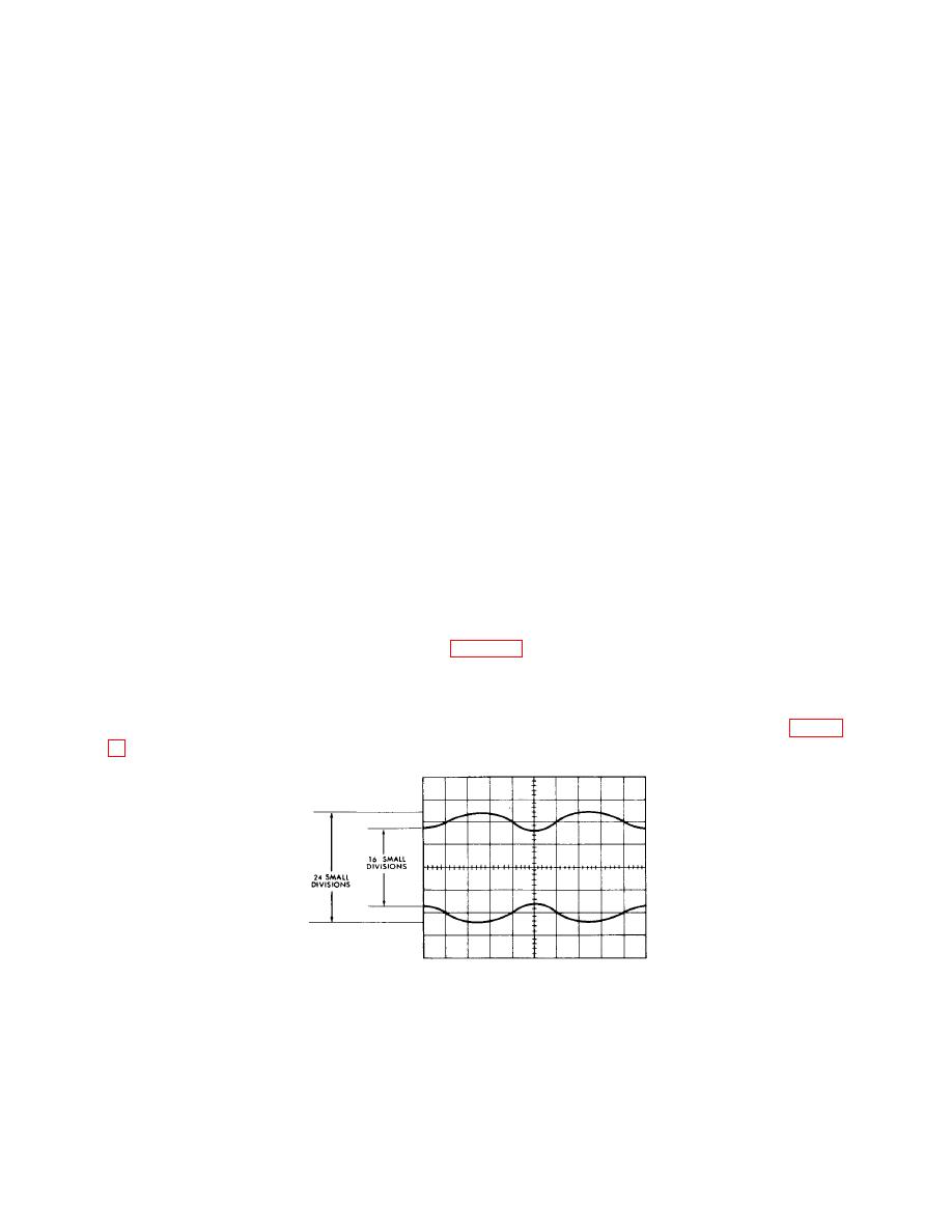
(13) Adjust oscilloscope as necessary. If oscilloscope display is not as shown in figure
Figure 6. Test instrument - 20-percent modulation waveform.
(14) Turn AUDIO SELECTOR to 150.
(15) Repeat (13) above.
12

