
TB 9-6625-100-24
(6) Place calibration resistor labeled SHORT in the remote test fixture.
(7) Perform TI short circuit compensation by completing (a) through (d) below.
(a) FUNCTION (if necessary) to select MEASURE.
(b) MEASURE MODE (if necessary) to select TRIGGERED.
(c) Press 1 6 9 3 = SHIFT SHORT. (GO indicator will light with "5" in the left
and right displays).
(d) Keep hands and objects at least 4 inches away from remote test fixture, then
press START button. (GO indicator extinguishes and lights again when complete).
(8) Remove calibration resistor labeled SHORT from the test fixture.
(9) Place first calibration resistor from table 5 in the remote test fixture.
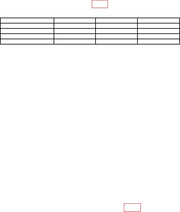
Table 5. Impedance Accuracy.
Calibration resistor (Ω)
Min (%)
Measured (%)
Max (%)
24.9
-0.02
+0.02
374
-0.02
+0.02
5.97 k
-0.02
+0.02
95.3 k
-0.02
+0.02
(10)Set TI to measure calibration resistor by completing (a) through (f) below.
(a) FUNCTION (if necessary) to select ENTER.
(b) DISPLAY (if necessary) to select Δ%.
(c) MEASURE RATE (if necessary) to select SLOW.
(d) MEASURE MODE (if necessary) to select CONT.
(e) EQUIVALENT CIRCUIT (if necessary) to select SERIES
(f) R/Q (if necessary) R in upper left must be lit.
NOTE
In step (11) below, the value of n must be entered in ohms
when the calibration resistor is either 24.9 Ω or 374 Ω (i.e.
24.9011 or 374.007). Entry must be made in kΩ when the
calibration resistor is either 5.97 kΩ or 95.3 kΩ (i.e. 5.96967 or
95.2932). In all cases, enter 6 digits of resolution though only 5
digits will be displayed.
(11)Enter value of calibration resistor by pressing n = SHIFT NOM VAL (where
n = present measured value of calibration resistor recorded in 7 b (7) with 6 digits of
resolution, i.e. 24.9011).
(12)Press TI FUNCTION key to select MEASURE.
(13) TI left display (%) will indicate within the limits of table 5. If not, perform b below.
7

