
TB 9-6625-1014-24
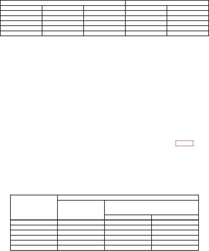
Table 3. LRC Dial Check - Continued
Test instrument LRC dial settings
Resistance standard indications (Ω)
Outer
Middle
Inner
Min
Max
6
0
0
5990
6010
7
0
0
6988.5
7011.5
8
0
0
7987
8013
9
0
0
8985.5
9014.5
10
0
0
9984
10,016
9. LRC Dial Multiplier
a. Performance Check
(1) Connect EXT DET terminals to INPUT terminals of dc detector (part of
resistance measurement system). Set DETECTOR switch to EXTERNAL.
(2) Connect resistance standard to L-R LO binding posts.
(3) Adjust LRC dials to 0.05 and set LRC DIAL MULTIPLIER switch to R-0.1 Ω.
(4) Adjust resistance standard for 0 Ω.
(5) Measure resistance of leads utilized in step (2) above, using TI and dc detector.
Record TI indication.
(6) Adjust resistance standard for 1 Ω.
(7) Adjust LRC dial for 0 indication on null meter. Record dial indication.
(8) Subtract value recorded in (5) above from value recorded in (7) above. Difference
will be between 0.9964 and 1.0036 Ω after multiplying LRC dials by LRC multiplier.
(9) Repeat technique of (6) through (8) above, using settings listed in table 4. TI Ω
values will be within limits specified.
NOTE
For values above 1000 Ω, it is not necessary to subtract value
obtained in (5) above.
b. Adjustments. No adjustments can be made.
Table 4. LRC Dial Multiplier Check
Test instrument
Resistance standard
LRC dial
Resistance (Ω)
indications
(LRC dials x LRC dial multiplier
multiplier switch
(Ω)
settings
switch settings)
Min
Max
(Ω)
10
1
9.984
10.016
100
10
99.84
100.16
1,000
100
998.4
1,001.6
10,000
1
k
9,984
10,016
100,000
10
k
99,840
100,160
1,000,000
100
k
997,900
1,002,100

