
TB 9-6625-1098-24
(7) Repeat (2) through (5) above, using TI control settings and frequencies listed in
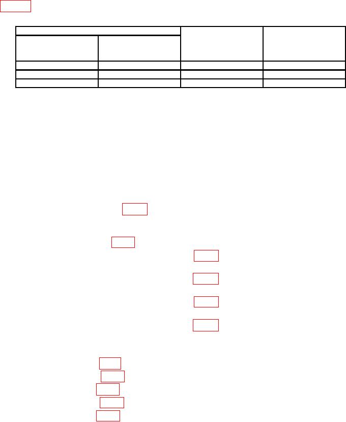
Table 9. Fundamental Frequency Rejection (Alternate Method)
Spectrum analyzer
Calibrator
Test instrument
center frequencies
frequencies
(kHz)
(kHz)
RANGE
dial settings
switch settings
X100
50
5
5
X1K
50
50
50
951
X10K
10
95
1Total
change will be at least 70 dB below indication recorded in (3) above.
b. Adjustments. No adjustments can be made.
19. Power Supply
a. Performance Check
NOTE
Do not perform power supply check if all other parameters are
within tolerance.
(1) Connect multimeter between TI chassis ground and pin 5 on circuit board A2
(pin 2 on circuit board A5) (fig. 1), using probe (B6). If multimeter does not indicate
between -24.5 and -25.5 V dc, perform b (1) below.
(2) Connect multimeter between TI chassis ground and pin 13 of circuit board A2
(pin 4 on circuit board A5) (fig. 1). Multimeter will indicate between +24.0 and +26.0 V dc.
(3) Connect multimeter between A2TP2 (fig. 1) and chassis ground. If multimeter
does not indicate between +7.7 and +8.7 V dc, perform b (2) below.
(4) Connect multimeter between A3TP1 (fig. 1) and chassis ground. If multimeter
does not indicate between +2.45 and +2.85 V dc, perform b (3) below.
(5) Connect multimeter between A3TP2 (fig. 1) and chassis ground. If multimeter
does not indicate between -19.9 and -20.5 V dc, perform b (4) below.
(6) Connect multimeter between A2TPI (fig. 1) and chassis ground. If multimeter
does not indicate between -11.2 and -11.4 V dc, perform b (5) below.
b. Adjustments
(1) Adjust A1R13 (fig 1) for a -25 V dc indication on multimeter (R).
(2) Adjust A2R20 (fig. 1) for a +8.2 V dc indication on multimeter (R).
(3) Adjust A3R4 (fig. 1) for a +2.65 V dc indication on multimeter (R).
(4) Adjust A3R16 (fig. 1) for a -20.2 V dc indication on multimeter (R).
(5) Adjust A2R3 (fig. 1) for a -11.3 V dc indication on multimeter (R).

