
TB 9-6625-1213-24
(3) Measure and record function/arbitrary generator distortion.
NOTE
Do not change function/arbitrary generator frequency or
output.
(4) Set GAIN switch to 20 dB and connect function/arbitrary generator to TI INPUT.
(5) Connect audio analyzer to TI OUTPUT. Audio analyzer will indicate less than
1 percent distortion after subtracting distortion recorded in 3 above.
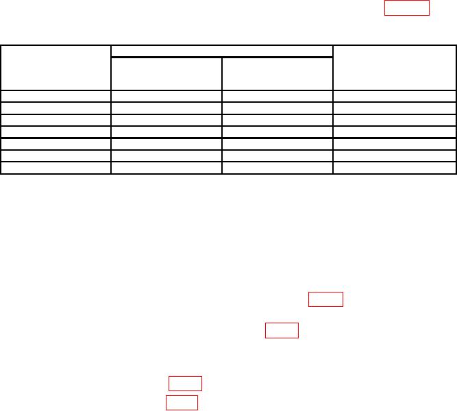
(6) Repeat technique (1) through (5) above at values listed in table 3. Audio
analyzer will indicate within limits specified.
Table 3. Distortion Check
Test instrument
Audio analyzer
Function/arbitrary generator
GAIN
indications (less
Output amplitude
switch settings
function/arbitrary
(V)
generator distortion)
20
1
kHz
1
Less than 1%
20
100
kHz
1
Less than 1%
20
600
kHz
1
Less than 2%
40
10
Hz
0.1
Less than 1%
40
1
kHz
0.1
Less than 1%
40
100
kHz
0.1
Less than 1%
40
600
kHz
0.1
Less than 2%
b. Adjustments. No adjustments can be made.
18. Power Supply
NOTE
Do not perform power supply check if all other parameters are
within tolerance.
a. Performance Check
(1) Connect multimeter between positive side of C20 (fig. 5) and chassis ground. If
multimeter does not indicate between 44 and 46 V, perform b (1) below.
(2) Move positive lead to positive side of C15 (fig. 5). If multimeter does not indicate
between 22.5 and 23.5 V dc, perform b (2) below.
b. Adjustments
(1) Adjust R32 +45 V ADJ (fig. 5) until multimeter indicates 45 V dc (R).
(2) Adjust R15 BIAS ADJ (fig. 5) until multimeter indicates 23 V dc (R).
19. Final Procedure
a. Deenergize and disconnect all equipment.
b. Annotate and affix DA label/form in accordance with TB 750-25.
11/(12 Blank)

