
TB 9-6625-127-24
Adjustments required to calibrate the TI are included in this procedure. Additional
maintenance information is contained in the manufacturers' manuals for this TI.
d. Unless otherwise specified, all controls and control settings refer to the TI.
7. Equipment Setup
HIGH VOLTAGE is used or exposed during the performance of
this calibration.
DEATH ON CONTACT may result if
personnel fail to observe safety precautions.
REDUCE
OUTPUT(S) to minimum after each step within the
performance check where applicable.
a. Press TI POWER button to turn TI on and allow 30 minute warm-up time.
b. Set TI controls as listed in (1) through (7) below:
MODE (Input) to NORM.
(1)
(2)
Function to square.
DTY to 50%.
(3)
CTRL to off.
(4)
AMP to 1 V.
(5)
OFS to 0 V.
(6)
COMPL (Output) to off.
(7)
8. Frequency
a. Performance Check
(1) Connect TI OUTPUT to frequency counter A input and set frequency counter for
50 Ω input.
(2) Set TI to first frequency listed in Applied column of table 3. If frequency counter
does not indicate within limits specified in table 3, perform b below.
(3) Repeat technique of (2) above for remaining frequencies listed in table 3. If
frequency counter does not indicate within limits specified in table 3, perform b below.
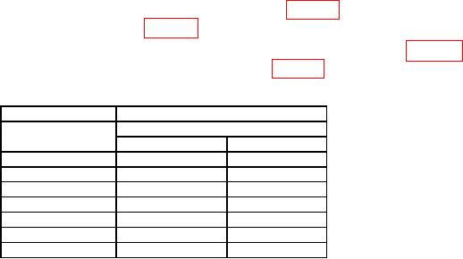
Table 3. Frequency
Test instrument
Frequency counter indication
Limits
Applied
Min
Max
50
MHz
47.500 MHz
52.500 MHz
10.0 MHz
9.500 MHz
10.500 MHz
1.0 MHz
0.950 MHz
1.050 MHz
10
kHz
9.700 kHz
10.300 kHz
1.0 kHz
0.970 kHz
1.030 kHz
1
1.00 Hz
0.9706 s
1.0312 s
100
mHz
9.681 s
10.341 s
Set frequency counter for period measurement.
1

