
TB 9-6625-133-40
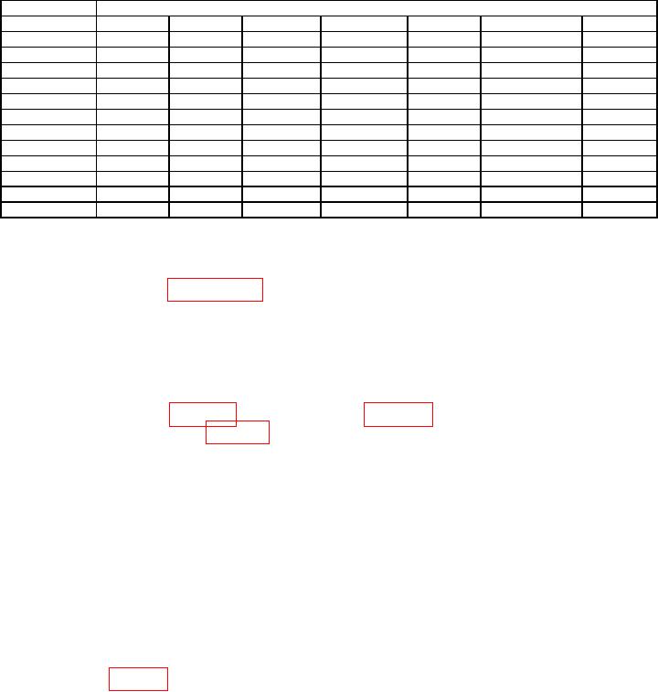
Table 3. ADC Verification.
Calibrator
TI
Output (V dc)
Reference
Indication
Min (uV)
Measured
Max (uV)
RESL
FAST
0.0
7
selected
-10
10
0.0
6
de-selected
-10
10
0.0
6
selected
-50
50
0.0
5
de-selected
-100
100
10
7
selected
-10
10
10
6
de-selected
-20
20
10
6
selected
-50
50
10
5
de-selected
-100
100
-10
7
selected
-10
10
-10
6
de-selected
-20
20
-10
6
selected
-50
50
-10
5
de-selected
-100
100
(14) Set calibrator output to minimum and disconnect equipment set-up.
b. Adjustments. Complete all performance checks in the entire procedure noting AS
FOUND failures. Use paragraph 15 a for adjustments.
9. DC Voltage and Linearity
a. Performance Check
NOTE
Use the same high quality low thermal emf leads during
zeroing (figure 1) and measuring (figure 2). After making
connection in figure 1, set TI to the 200 mV dc range, allow
time for thermals to dissipate and TI indications to stabilize
before activating zero. This could take several minutes.
Significant errors may be introduced into low voltage
measurements by offset voltages and noise sources.
Precautions should be taken to minimize personnel movements
and temperature gradients in or near the system which cause
error voltages, potentially on the order of several microvolts.
When measuring 100 mV for example, 1 microvolt equates to
10 ppm, an out of tolerance indication. If an out of tolerance
condition is noted, particularly on the 200 mV dc range, check
zero and re-zero if necessary before making any adjustments.
(1) Prepare TI for zeroing by shorting leads to a low thermal binding post such as
that shown in figure 1.

