
TB 9-6625-1360-24
e. Turn frequency counter off and wait 1 minute. If meter pointer on TI does not
indicate 0 (zero), remove TI from frequency counter and adjust to 0 (zero) by turning
adjustment screw located in hole on top-rear of meter.
f. Repeat a above.
g. Energize equipment and allow sufficient time for equipment to warm-up and
stabilize.
8. Frequency and Sensitivity
a. Performance Check
(1) Connect signal generator to INPUT connector of TI, using adapter and cable.
(2) Adjust signal generator output to 55 MHz at 100 mV.
(3) Turn TI frequency dial to 50 and tune frequency dial for maximum indication in
green portion of meter scale. Frequency counter will indicate approximately 5 MHz.
(4) Reduce signal generator output voltage until TI level indicator meter indicates
at red-green border. Frequency counter indication will remain at approximately 5 MHz and
signal generator output voltage will be 50 mV or less.
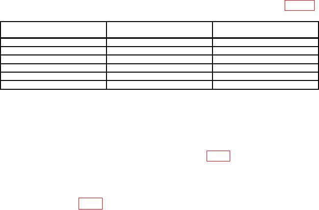
(5) Repeat (2) through (4) above, using settings and indications listed in table 3.
Table 3. Frequency Check
Signal generator setting
Test instrument
Frequency counter indication
(MHz)
dial setting
(MHz)
115
110
5
155
150
5
205
200
5
305
300
5
405
400
5
475
470
5
b. Adjustments
(1) Remove TI from frequency counter and reconnect, using extension cable (B3).
(2) Repeat a (1) above.
(3) Adjust signal generator for an output of 472 MHz at 100 mV.
(4) Connect multimeter to XA1 pin 15 of connector (fig. 1).
(5) Turn frequency dial to 470 and tune for maximum indication on multimeter.
(6) Adjust signal generator output voltage until TI level indicator meter indicates at
red-green border.
(7) Adjust A3C5 (fig. 2) for maximum indication on multimeter (R).

