
TB 9-6625-149-50
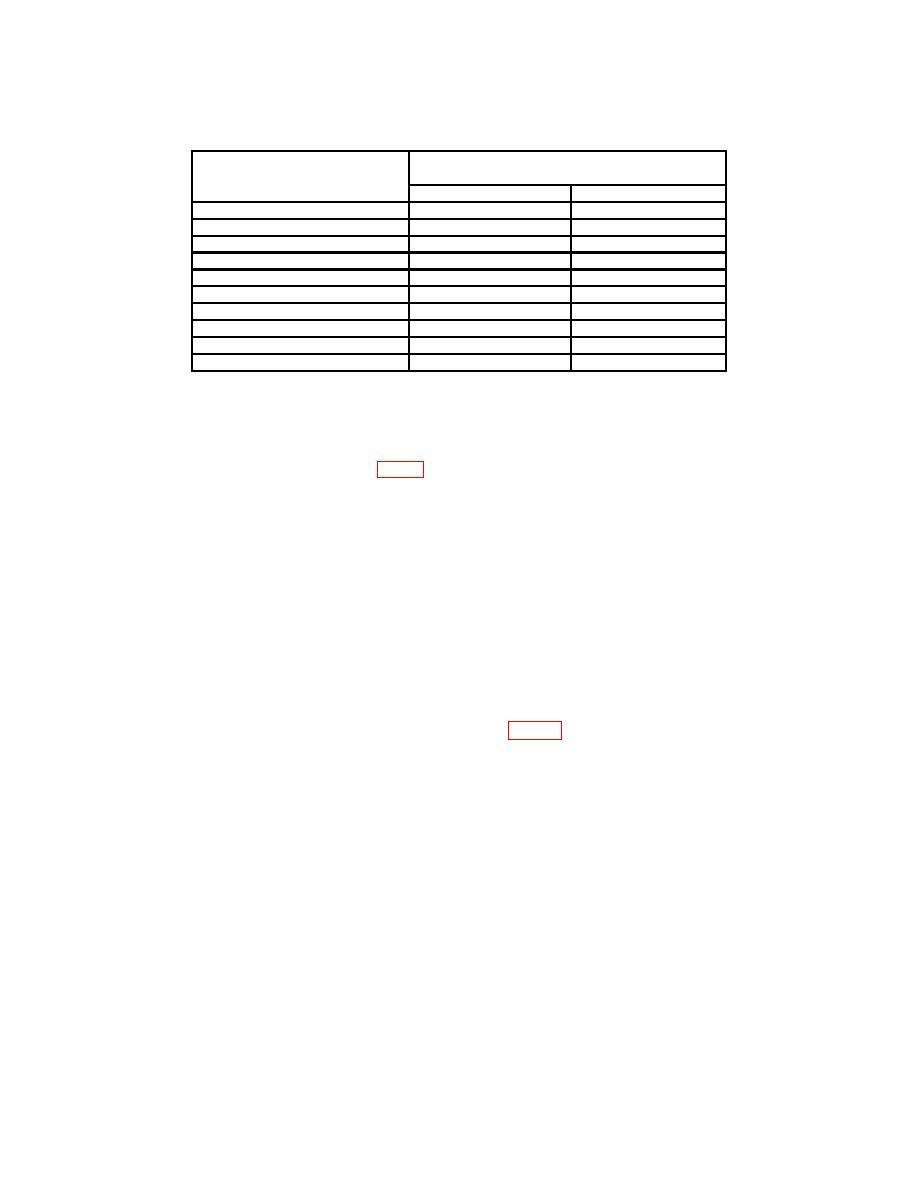
Table 4. Calibrator Accuracy
Test instrument
Ac/dc voltmeter indication
(+ V dc)
AMPLITUDE CALIBRATOR
switch settings
Min
Max
100 VOLTS
97
103
50 VOLTS
48.5
51.5
20 VOLTS
19.4
20.6
10 VOLTS
9.7
10.3
5 VOLTS
4.85
5.15
2 VOLTS
1.94
2.06
1 VOLT
0.97
1.03
.5 VOLT
0.485
0.515
.2 VOLT
0.194
0.206
.1 VOLT
0.097
0.103
b. Adjustments
(1) Turn AMPLITUDE CALIBRATOR switch to 100 VOLTS.
9. Crt Geometry
a. Performance Check
(1) Connect TI CAL OUT to calibration adapter (A4) EXT INPUT, using cable (B5)
and, if necessary, adapter (B2).
(2) Set AMPLITUDE CALIBRATOR switch to 5 VOLTS.
(3) Adjust calibration adapter VERTICAL POSITION control until only the rising
and falling portion of display are visible on TI crt. If vertical curvature of display is
observed, perform b below.
display.
10. Vertical Amplifier Gain and Stability
a. Performance Check
(1) Connect ac calibrator (A1) to calibration adapter (A4) EXT INPUT, using cable
(B4).
(2) Turn calibration adapter TEST FUNCTION switch to GAIN SET.
(3) Adjust ac calibrator controls for 1 kHz and amplitude for 4 major divisions of
vertical deflection on TI crt. If ac calibrator does not indicate between 34.29 and 36.41
volts rms, perform b below.
8

