
TB 9-6625-1997-24
FUNCTION switch to MOD OFF.
(a)
RF OUTPUT switch to 0-10 KUV.
(b)
LO RF UV dial to 10 KUV.
(c)
BAND SWITCH to A.
(d)
RF TUNING control to 20.
(e)
(3) Adjust LO-HI RF SET TO LINE control for a red-line indication on IF UV RF
SET TO LINE meter. If measuring receiver does not indicate within limits shown in first
row of table 5, perform b below.
(4) Repeat technique of (2) and (3) above for switch settings listed in table 5. If
measuring receiver does not indicate within limits specified, perform b below.
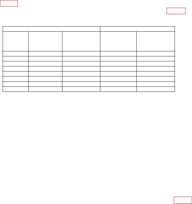
Table 5. Low RF Voltage Range Accuracy
Test instrument
Measuring receiver
RF TUNING
LO RF UV
BAND
control for
dial for
SWITCH
output
Min
Max
setting
(MHz)
(KUV)
(mV)
(mV)
A
20
10
8.5
11.5
3
2.55
3.45
B
30
10
8.5
11.5
3
2.55
3.45
C
45
10
8.5
11.5
3
2.55
3.45
D
65
10
8.5
11.5
3
2.55
3.45
b. Adjustments
(1) Turn LO RF UV dial to 10 KUV and adjust LO-HI RF SET TO LINE control
for a 10.00 mV indication on measuring receiver.
(2) Adjust R61 (LO RF METER CAL) for a red-line indication on IF MV RF SET
TO LINE meter (adjustment is located on right end on bottom chassis) (R).
10. High RF Voltage Range
a. Performance Check
HI-RF, using cable No. 2.
NOTE
At each of the following tests, adjust LO-HI RF SET TO LINE
control to maintain red line indication on IF MV RF SET TO
LINE meter.
(2) Set RF OUTPUT switch to 62.5 KUV and BAND SWITCH to B and 30 MHz.
If measuring receiver does not indicate within the limits shown in first row of table 6,
perform b below.

