
TB 9-6625-2000-35
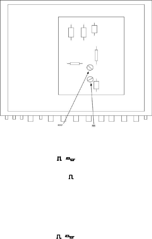
Figure 2. Model 1020A-Y - adjustment locations (top view).
12. Waveforms
a. Performance Check
(1) Connect oscilloscope to TI
OUT.
(2) Set RATE control fully cw, and X1-X10-X100 switch to X100. Oscilloscope will
indicate a square wave.
(3) Set FUNCTION switch to INT
and PULSE WIDTH control fully ccw and X1-
X10-X200-X1000 switch to X1. Oscilloscope will indicate a pulse width (pip) less than 0.2 s.
(4) Set PULSE WIDTH control fully cw. Oscilloscope will indicate a pulse width 2 s
or more.
(5) Set PULSE WIDTH X1-X10-X200-X1000 switch to X10. Oscilloscope will indicate
a pulse width 20 s or more.
(6) Set PULSE WIDTH X1-X10-X200-X1000 switch to X200 and RATE X1-X10-X100
switch to X1. Oscilloscope will indicate a pulse width 400 s or more.
(7) Set PULSE WIDTH X1-X10-X200-X1000 switch to X1000.
Oscilloscope will
indicate a pulse width 2,000 s or more.
(8) Disconnect cable from TI
OUT and connect to FM OUT.

