
TB 9-6625-2011-24
(b) PULSE DELAY(S) switch to 35n-1
(c) PULSE WIDTH(S) switch to 10n-1 .
(3) Adjust PULSE WIDTH VERNIER control fully cw. Measure pulse width,
using standard measurement technique. If oscilloscope does not indicate a pulse width
between 1.1 and 1.5 s, perform b below.
(4) Repeat technique of (2) and (3) above, using TI settings listed in table 5. Pulse
width will be within limits specified.
Table 5. Pulse Width
Test instrument
PULSE
PULSE
PULSE WIDTH
WIDTH
PERIOD(S)
VERNIER
Oscilloscope
switch settings
switch settings
control positions
indications
0.1 m - 10m
cw
>0.1
ms
1 - . 1m
s
ccw
1 - . 1m
1 - . 1m
<1
0.1 m - 10m
10 m - 1
cw
>10
ms
0.1 m - 10m
0.1 m - 10m
ccw
<0.1
ms
(+) EXT
10 m - 1
cw
>1
s
(Press MAN)
10 m - 1
10 m - 1
ccw
<10
ms
20 n-1
ccw
10
l0 n-1
ns
b. Adjustments. Adjust A5C45 (fig. 1) for a pulse width of 1.3 s. (R).
11. Pulse Shape
a. Performance Check
(1) Set pulse width to SQUARE WAVE.
(2) Measure rise and falltime, using standard measurement technique. Rise and
falltime, as indicated on oscilloscope, will be less than 3.5 ns.
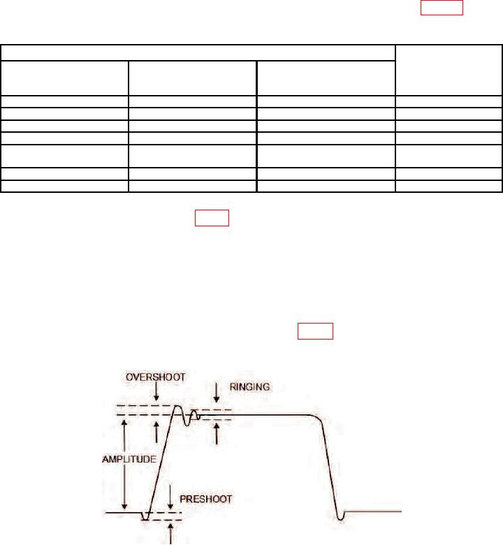
(3) Measure preshoot, overshoot, and ringing (fig. 4), using standard measurement
technique. If preshoot, overshoot and ringing, are not less than 5 percent of pulse
amplitude, perform b (1) below.
Figure 4. Output pulse characteristics.

