
TB 9-6625-2059-24
10. Output Level
a. Performance Check
(1) Set FREQUENCY MHz switches to 100 000 0 and HI LVL - V X100-NORM
switch to HI LVL.
(2) Adjust BFO-RF LEVEL control until TI 0 dBm light just illuminates.
(3) Configure measuring receiver to measure power. Zero and calibrate measuring
receiver sensor module. Connect sensor module to TI TRANS-RCVR.
(4) Set measuring receiver to read frequency and then for tuned RF level measurement.
(5) Measuring receiver will indicate between -2.5 and +2.5 dB.
(6) Set HI LVL - VX100-NORM switch to VX100 and adjust BFO-RF LEVEL to
the first setting in table 7. If measuring receiver does not indicate within limits specified in
first row of table 7 perform b below.
NOTE
If measuring receiver cannot maintain phase lock, check TI
residual FM performance as outlined in paragraph 16 below.
Rerun paragraph 10 using an appropriate low pass filter.
(7) Repeat technique of (6) above for BFO-RF LEVEL control settings and
FREQUENCY MHz switch settings at 100 000 0 listed in table 7. Measuring receiver will
indicate within limits specified.
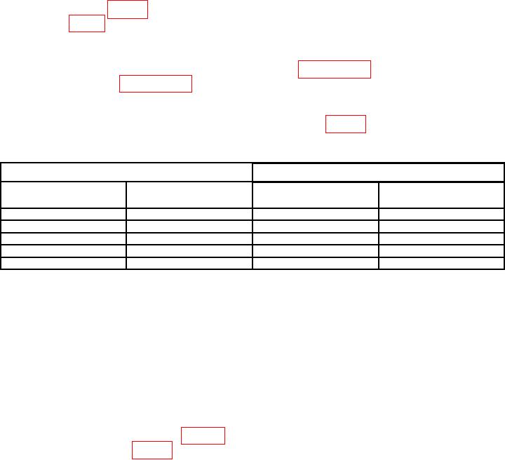
Table 7. Output Level 100 MHz.
Test instrument
Measuring receiver indications (dB)
BFO-RF LEVEL
FREQUENCY MHz
Min
Max
control settings
switch settings
80
100 000 0
-37.5
-42.5
90
100 000 0
-47.5
-52.5
100
100 000 0
-57.5
-62.5
110
100 000 0
-67.5
-72.5
120
100 000 0
-77.5
-82.5
(8) Set HI LVL - VX100-NORM switch to NORM and BFO-RF LEVEL control
to -80 dBm. Measuring receiver will indicate between 77.5 and 82.5 dB.
(9) Set FREQUENCY MHz switches to 250 000 0 and HI LVL - VX100-NORM
switch to HI LVL.
(10) Adjust BFO-RF LEVEL control until TI 0-dBm light just illuminates.
(11) Repeat (4) above.
(12) Measuring receiver will indicate between -4.0 and +4.0 dB.
(13) Set HI LVL - VX100-NORM switch to VX100 and adjust BFO-RF LEVEL
control to the first setting in table 8. Measuring receiver will indicate within limits
specified in first row of table 8.

