
TB 9-6625-2072-24
Table 5. Input Capacitance and Attenuator Compensation
Test instrument
Channel A
Channel B
VOLTS/DIV
adjustments
adjustments
switch settings
0.01
C120
C220
0.02
C125
C225
0.05
C103
C203
C105
C205
0.1
C118
C218
0.2
C123
C223
0.5
C107
C207
C109
C209
5
C112
C212
C114
C214
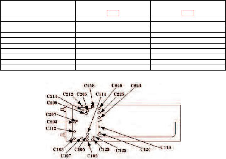
Figure 3. Dual channel vertical amplifier - bottom view.
(7) Disconnect oscilloscope calibrator from A INPUT and connect to B INPUT.
(8) Set DISPLAY switch to B and repeat technique of (2) through (6) above for
channel B.
b. Adjustments. No further adjustments can be made.
18. Final Procedure
a. Deenergize and disconnect all equipment and reinstall protective cover on TI.
b. Annotate and affix DA label/form in accordance with TB 750-25.

