
TB 9-6625-2083-24
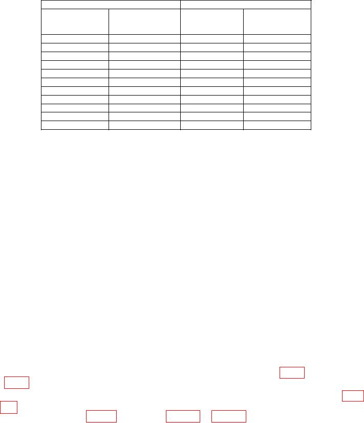
Table 4. Vertical Gain CH 2
Test instrument
Oscilloscope calibrator
Err display
VOLTS/DIV
VOLTAGE
Divisions of vertical
Indication limits
setting
deflection
output
(%)
20 mV
5
100 mV
3
5 mV
4
20 mV
3
10 mV
5
50 mV
3
50 mV
4
0.2 V
3
0.1 V
5
0.5 V
3
0.2 V
5
1 V
3
0.5 V
4
2 V
3
1 V
5
5 V
3
2 V
5
10 V
3
5 V
4
20 V
3
10 V
5
50 V
3
b. Adjustments
(1) Rotate oscilloscope calibrator knob located below EDIT FIELD pushbutton for
Err display of 0.0%.
(2) Adjust CH 1 GAIN (front panel) for 5 divisions of vertical deflection.
(3) Rotate oscilloscope calibrator knob located below EDIT FIELD pushbutton for
Err display of 0.0%.
(4) Adjust CH 2 GAIN (front panel) for 5 divisions of vertical deflection.
9. VOLTS/DIV Compensation
a. Performance Check
(1) Connect oscilloscope calibrator SOURCE/MEASURE CHAN 1 to TI CH 1
INPUT and CHAN 2 to TI CH 2 INPUT through 50 feed-through terminations and
5 80pF standardizers.
(2) Set TI CH 1 and CH 2 VOLTS/DIV switches to 20 mV and MODE switch to
CH 1.
(3) Set oscilloscope calibrator for a CHAN 1, EDGE mode output of 100 mV, and
frequency of 1 kHz. Rotate oscilloscope calibrator knob located below EDIT FIELD
pushbutton for 5 divisions of vertical deflection on TI.
(4) Adjust standardizer for optimum square corner and flat top indication on TI. If
standardizer cannot be adjusted for optimum square wave, adjust C17 (fig. 1 for Type 453)
(fig. 2 for Type 453A) for flat top and readjust standardizer for optimum square wave (R).
(5) Repeat technique of (3) above for TI VOLTS/DIV switch settings listed in table
5. If oscilloscope does not display square corners and flat tops, perform appropriate

