
TB 9-6625-2088-24
15. Power Supply
NOTE
Do not perform power supply check if all other parameters are
within tolerance.
a. Performance Check
NOTE
Some models do not contain all of the power supply test points
or adjustments. Perform only those that are available or
accessible (see paragraph 1 a above).
(1) Connect multimeter to test points listed in table 7. If multimeter does not
indicate within limits specified, perform corresponding adjustments and adjust for best in-
tolerance condition.
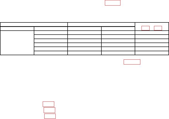
Table 7. Power Supply
Test points (figs. 3 and 4)
Multimeter indications (V dc)
Adjustments
Common
Positive
Min
Max
TP1
TP2
14.98
15.02
R27 (R)
TP3
-14.95
-15.05
---
TP4
23.00
25.00
---
TP5
-23.00
-25.00
---
TP6
4.80
5.20
---
TP7
-5.19
-5.21
R18 (R)
(2) Connect multimeter between TP5 (common) and TP1 in figure 2. If multimeter
does not indicate less than 5 mV dc, perform b (1) below.
(3) Connect multimeter to FUNCTION OUT using 50
feedthrough termination.
If multimeter does not indicate 0 0.01 V dc, perform b (2) below.
(4) Repeat (3) above except set ATTENUATION VERNIER control fully cw. If
multimeter does not indicate 0 0.01 V dc, perform b (3) below.
b. Adjustments
(1) Adjust R55 (fig. 2) for minimum indication less than 5 mV. (R)
(2) Adjust R181 (fig. 2) for zero volt 0.01 V. (R)
(3) Adjust R252 (fig. 2) for zero volt 0.01 V. (R)

