
TB 9-6625-2089-24
(5) Adjust oscilloscope controls as required to display second pulse and count the
number of markers to same reference point on the leading edge of second CH1 input pulse.
Multiply number of markers by 0.1 μs to obtain pulse spacing. Pulse spacing will be
between 2.95 and 3.05 μs.
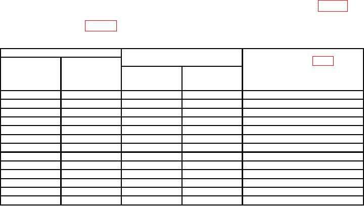
(6) Repeat technique of (3) through (5) above for control settings listed in table 6. If
pulse spacing as indicated on oscilloscope is not within limits specified, perform
adjustments listed in table 6.
Table 6. Challenge Code Accuracy
Oscilloscope indications
Test instrument
spacing (μS)
Adjustments (fig. 1)
CHAL SUB
(R)
CHAL MODE
PULSE
(μS)
SELECT
POSITION
Min
Max
SELECT
1
-.9
3.85
3.95
A6R5 for 3.9
1
-.2
3.15
3.25
A6R6 for 3.2
1
+.2
2.75
2.85
A6R7 for 2.8
1
+.9
2.05
2.15
A6R8 for 2.1
<2.01
>4.02
1
VARY`
---
2
+.9
4.05
4.15
---
2
0
4.95
5.05
---
3/A
0
7.95
8.05
---
3/A
+.9
7.05
7.15
---
C
+.9
20.05
20.15
---
C
0
20.95
21.05
---
TEST
0
6.45
6.55
A6R21 for 6.5
TEST
+.9
5.55
5.65
---
1Adjust
VARY control fully cw.
2Adjust
VARY control fully ccw.
(7) Position switches as listed in (a) through (c) below:
(a) CHAL MODE SELECT to 4A.
(b) CHAL WIDTH SELECT to 0.50.
(c) PRF SELECT to X1/2.
(8) Oscilloscope CH1 will display a pulse train (Challenge Word) consisting of 28 pulses.
(9) Set CHAL, SUB PULSE SELECT switch to M4P2 and observe second pulse of
train. Second pulse of train will move out of position.
(10) Set CHAL SUB PULSE SELECT switches to M4P3. Second pulse of train will
return to original position and third pulse of train will move out of position.
(11) Set CHAL SUB PULSE SELECT switch to M4P4. Third pulse of train will
return to original position and fourth pulse of train will move out of position.
(12) Set CHAL SUB PULSE POSITION SELECT switch to 0. Adjust oscilloscope
controls until twenty-eight pulses are displayed on oscilloscope crt. Using technique of (3)
through (5) above, verify that pulses are present at 0, 2, 4, 6, 10, 13, 15, 17, 20, 24, 26, 30,
33, 35, 38, 41, 43, 45, 48, 50, 52, 54, 58, 61, 63, 66, 68, and 71 μs positions.
14

