
TB 9-6625-2099-24
rotate oscilloscope calibrator knob located below EDIT FIELD pushbutton to obtain
display will indicate within limits specified in table 4; if not, perform b below.
(15) Repeat technique of (11) through (14) above for remaining rows listed in table 4.
Oscilloscope calibrator err display indications will be within limits specified in table 4.
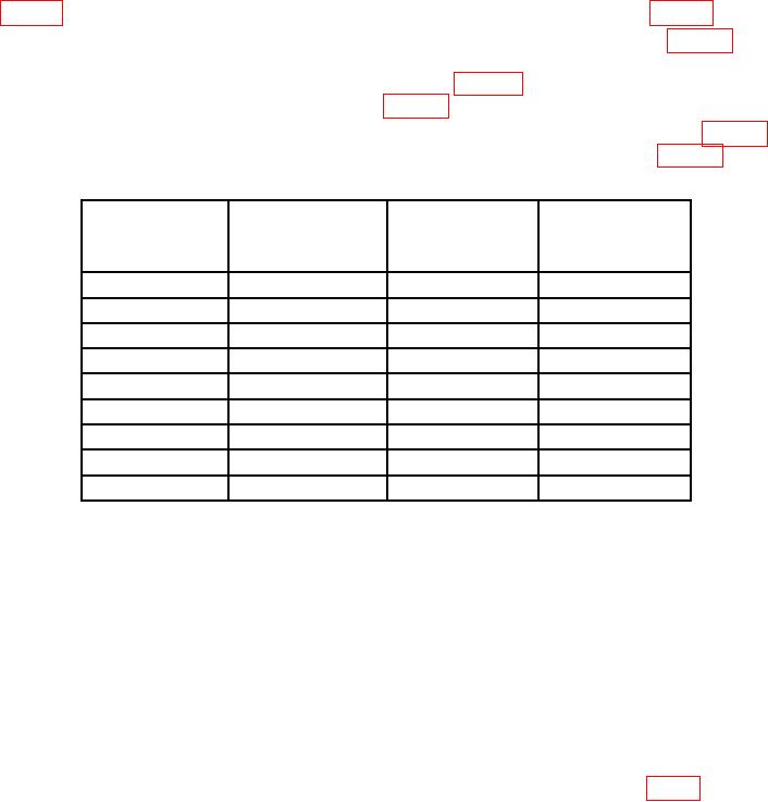
Table 4. Ch 2 Vertical Gain
Oscilloscope
Test instrument
Oscilloscope calibrator
Test
calibrator
VOLTS/DIV
Voltage
Err display limits
instrument
switch settings
output
display divisions
(%)
5
mV
20
mV
4
2
20
mV
0.1
V
5
2
50
mV
0.2
V
4
2
0.1
V
0.5
V
5
2
0.2
V
1
V
5
2
0.5
V
2
V
4
2
1
V
5
V
5
2
2
V
10
V
5
2
5
V
20
V
4
2
(16) Deenergize oscilloscope and remove TI from left vertical compartment and
reinstall, using extender.
(17) Energize oscilloscope.
(18) Set CH 1 VOLTS/DIV switch to 5 mV and DISPLAY MODE switch to CH 1.
(19) Ensure oscilloscope calibrator CHAN 1 is connected to CH 1 using a 5-80 pF
standardizer. Press oscilloscope calibrator CHANNEL pushbutton and press blue soft
pushbutton located below CHAN 1.
(20) Set oscilloscope calibrator EDGE output frequency to 1 kHz.
(21) Adjust oscilloscope calibrator output for 6 divisions of display.
(22) Adjust standardizer for optimum square wave. If optimum square wave cannot
be obtained, adjust CHANNEL 1 C100 (CH 2 adjust C100 CHANNEL 2) (fig. 1 or 2) to
midrange and readjust standardizer for optimum square wave.
6

