
TB 9-6625-2134-24
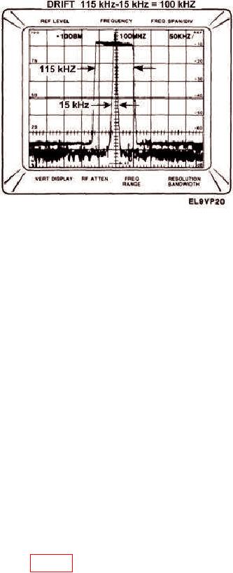
Figure 32. Frequency Drift Measurement.
b. Adjustments. No adjustments can be made.
22. Noise Sidebands
a. Performance Check
(1) Position controls as listed in (a) through (h) below:
(a)
FREQUENCY RANGE pushbutton to BAND 1.
(b)
FREQUENCY SPAN/DIV control to 20 MHz.
(c)
VERTICAL DISPLAY 10 dB/DIV pushbutton to on.
(d)
TIME/DIV switch to AUTO.
(e)
REFERENCE LEVEL control to -20 dBm.
(f)
AUTO RESOLUTION pushbutton to on.
(g)
VERTICAL DISPLAY 10 dB/DIV pushbutton to on.
(h)
DIGITAL STORAGE (option 02) VIEW A/VIEW B pushbutton to on.
(2) Connect CAL OUT to RF INPUT.
(3) Center one of the CAL OUT markers on crt with FREQUENCY control and
adjust REFERENCE LEVEL control for a full screen display. Keep CAL OUT marker
centered on screen as FREQUENCY SPAN/DIV control is reduced to 10 kHz and
RESOLUTION BANDWIDTH control is decreased to 1 kHz. If option 03 is installed,
note that PHASELOCK pushbutton is on.
(4) Increase REFERENCE LEVEL control to -40 dBm to position the signal peak 20
dB above reference line on crt. Check amplitude of noise sidebands 30 times the resolution
bandwidth away from signal (fig. 33). Noise sidebands will be 75 dB or more below peak
signal level or 55 dB below top of screen.
(5) Decrease FREQUENCY SPAN/DIV control to 1 kHz and RESOLUTION
BANDWIDTH control to 100 Hz. Check amplitude of noise sidebands 3 kHz away from
signal. Noise sidebands will be 70 dB below signal level or 50 dB below top of screen.

