
TB 9-6625-2155-24
h. Replace TI top cover.
i. Disconnect frequency
difference
meter
from
the
TI
and
the
GPS
time/frequency workstation.
8. Display Resolution and Accuracy
a. Performance Check
(1) Connect 10 MHz output of GPS time/frequency workstation to EXT REF IN of
the measuring receiver. Connect the TI RF OUTPUT to the measuring receiver INPUT.
(2) Press TI keys as listed in (a) through (f) below.
RCL 0.
(a)
Adjust OUTPUT LEVEL for 0 dB.
(b)
ALC INTERNAL on.
(c)
RF OUTPUT on.
(d)
FREQ INCR, 1, kHz.
(e)
FREQUENCY, 4, GHz.
(f)
(3) Configure the measuring receiver for a frequency measurement.
(4) Record the measuring receiver frequency indication as Reference.
(5) Calculate the minimum and maximum limits for the 4 GHz rows in table 3 using
the formula below:
Minimum = (Reference + TI increment amount) FREQ INCR setting
Maximum = (Reference + TI increment amount) + FREQ INCR setting
(6) Press the TI FREQ INCREMENT up arrow key three times as indicated in
table 3, and verify that the indication is within the limits calculated in (5) above.
(7) Press the TI FREQ INCREMENT down arrow key four times as indicated in
table, and verify that the indication is within the limits calculated in (5) above.
(8) Repeat (3) through (7) above for settings of FREQUENCY 8 GHz with FREQ
INCR of 2 kHz, and FREQUENCY 15 GHz with FREQ INCR of 3 kHz.
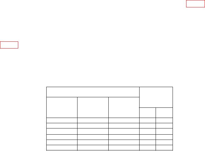
Table 3. Frequency Increment
Test instrument
Step
Tolerance
Frequency
increment
Increment
(GHz)
direction
amount
Min
Max
4.000000
UPUPUP
.003
4.000000
DNDNDNDN
-.001
8.000000
UPUPUP
.006
8.000000
DNDNDNDN
-.002
15
UPUPUP
.009
15
DNDNDNDN
-.003

