
TB 9-6625-2157-24
(3) Adjust RF OR PULSE LEVEL control until TI meter indicates 0.5 V.
If
oscilloscope does not indicate at least 1.5 V p-p, perform b (1) and (2) below.
(4) Adjust RF OR PULSE LEVEL control until TI meter indicates -3 dB.
If
oscilloscope does not indicate 1.05 V p-p or less, perform b (3) through (5) below.
b. Adjustments
(1) Adjust RF OR PULSE LEVEL control until oscilloscope indicates 1.5 V p-p.
(3) Adjust RF OR PULSE LEVEL control until oscilloscope indicates 1.05 V p-p.
(5) Repeat a (3) and (4) above.
14. Power Supply (Version A)
NOTE
Do not perform power supply check if all other parameters are
within tolerance.
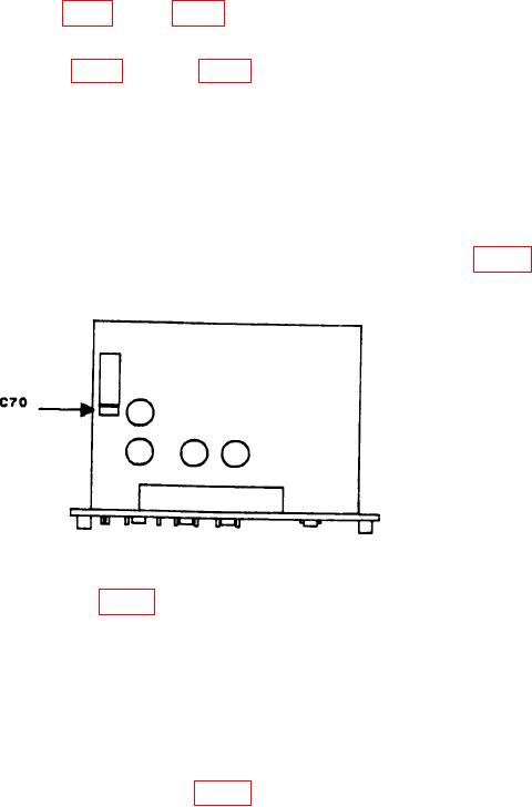
a. Performance Check. Connect multimeter between plus side of C70 (fig. 4) and
ground. If multimeter does not indicate between 19.5 and 20.5 V dc, perform b below.
Figure 4. Test instrument, version A bottom view.
b. Adjustments. Adjust R113 (fig. 1) until multimeter indicates 20.0 V dc (R).
15. Power Supply (Version B)
NOTE
Do not perform power supply check if all other parameters are
within tolerance.
a. Performance Check
(1) Connect multimeter between TP1 (fig. 3) and ground. If multimeter does not
indicate between 19.5 and 20.5 V dc, perform b (1) below.

