
TB 9-6625-2164-24
v. Remove all connections from TI.
w. Press MENU/TEST and MEMORY DISPLAY 4, 5, 6 and MENU/TEST pushbuttons.
x. Set CH 1 VOLTS/DIV switch to 100 mV.
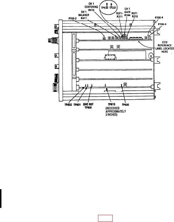
Figure 2. Tektronix, Type 7D20 top view - adjustment locations.
y. Press CH 1 DC pushbutton.
z. Set TIME/DIV switch to 20 s.
aa. Press TRIGGERING/MODE AUTO pushbutton.
ab. Press TRIGGERING/COUPLING AC and HF REJ pushbutton.
t ac. Connect function/arbitrary generator Output to CH 1 input, using 50
ermination, and set for Sine operation.
divisions on TI display.
ae. Set CH 1 VOLTS/DIV switch to 2V.
af. Adjust TRIGGERING/LEVEL control for a stable trigger. If trigger cannot be
obtained, adjust HYSTERESIS R444 (fig. 3) so a stable trigger can be obtained.
CHANGE 1

