
TB 9-6625-2170-24
(2) Position controls as listed in (a) through (e) below:
(a) INPUT RANGE switch to AUTO RANGE.
(b) FUNCTION VOLTS pushbutton pressed.
(c) FUNCTION LEVEL pushbutton pressed.
(d) RESPONSE RMS/AVG pushbutton pressed to RMS.
(e) All FILTERS pushbuttons released.
(3) Press and release signal generator OUTPUT ON/OFF pushbutton to OFF.
(4) Set calibrator for a 3 mV, 7 kHz output. Adjust calibrator amplitude for a
3.00 mV TI indication.
(5) Position signal generator FREQUENCY Hz controls for 400 Hz. Press signal
generator OUTPUT ON/OFF pushbutton to ON and position OUTPUT LEVEL (dBm)
controls for a 300 mV TI indication.
(6) Press FUNCTION THD + N pushbutton. If TI does not indicate between 0.9
and 1.1%, perform b below.
(7) Press FUNCTION LEVEL pushbutton.
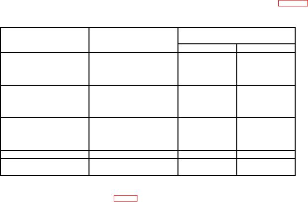
(8) Repeat technique of (3) through (7) above using frequencies listed in table 7. TI
will indicate within limits specified.
Table 7. Distortion Accuracy
Calibrator
Signal generator
Test instrument indications
FREQUENCY Hz
frequency
(%)
settings
settings
Min
Max
40
Hz
60
Hz
20 Hz
0.9
1.1
80
Hz
1
kHz
2
kHz
3
kHz
1 kHz
0.9
1.1
4
kHz
10
kHz
40
kHz
60
kHz
20 kHz
0.9
1.1
80
kHz
100
kHz
100
Hz
10 Hz
0.8
1.2
200
kHz
100 kHz
0.8
1.2
300
kHz
b. Adjustments. Adjust R1051 (fig. 1) until TI indicates 1.00% (R).

