
TB 9-6625-2224-24
NOTE
Before INTERNAL ALC pushbutton is pressed to in position
in (4) below, DBM meter should indicate approximately +1 dBm.
(4) Press INTERNAL ALC pushbutton to in position and adjust ALC CAL
OUTPUT control for a 0 indication on DBM meter. Power meter will indicate between -8.8
and -11.2 dBm. Record power meter indication.
(5) Adjust FREQUENCY (MC) control from 1800 to 4500. If power meter
indication does not remain within 1.0 dB of indication recorded in (4) above, perform b below.
and perform corresponding adjustment for a -10 dBm power meter indication.
NOTE
R614 and R621 interact as do R615 and R620. To simplify the
adjustment, overcorrect when adjusting R614 or R615, then
back off with interacting adjustment R621 or R620.
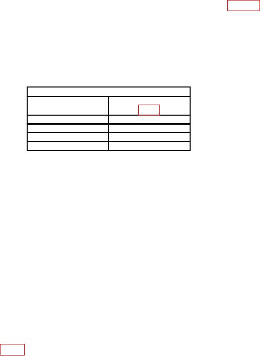
Table 7. Leveled Output Adjustments
Test instrument
Adjustments
FREQUENCY(MC)
dial settings
1800
R614
3200 below switch
R621
3200 above switch
R615
4500
R620
13. Internal Square Wave
a. Performance Check
(1) Position controls as listed in (a) through (d) below:
RF pushbutton released to out position.
(a)
INTERNAL ALC pushbutton released to out position.
(b)
FREQUENCY (MC) control to 0800 (1800).
(c)
ATTENUATION (DB) control to 000.
(d)
(2) Connect microwave frequency counter to RF POWER OUTPUTS CAL, using
crystal detector.
(3) Press RF and INTERNAL SQ WAVE pushbuttons to in position. Adjust SQ
WAVE control fully ccw. If microwave frequency counter does not indicate 950 Hz or less,
perform b below.
(4) Adjust SQ WAVE control fully cw. If microwave frequency counter does not
indicate 1050 Hz or greater, perform b below.
b. Adjustments. Adjust SQ WAVE control to center position. Adjust SQ WAVE
SYM. ADJ. R410 (fig. 2) for 1000 Hz indication on microwave frequency counter (R).

