
TB 9-6625-2235-24
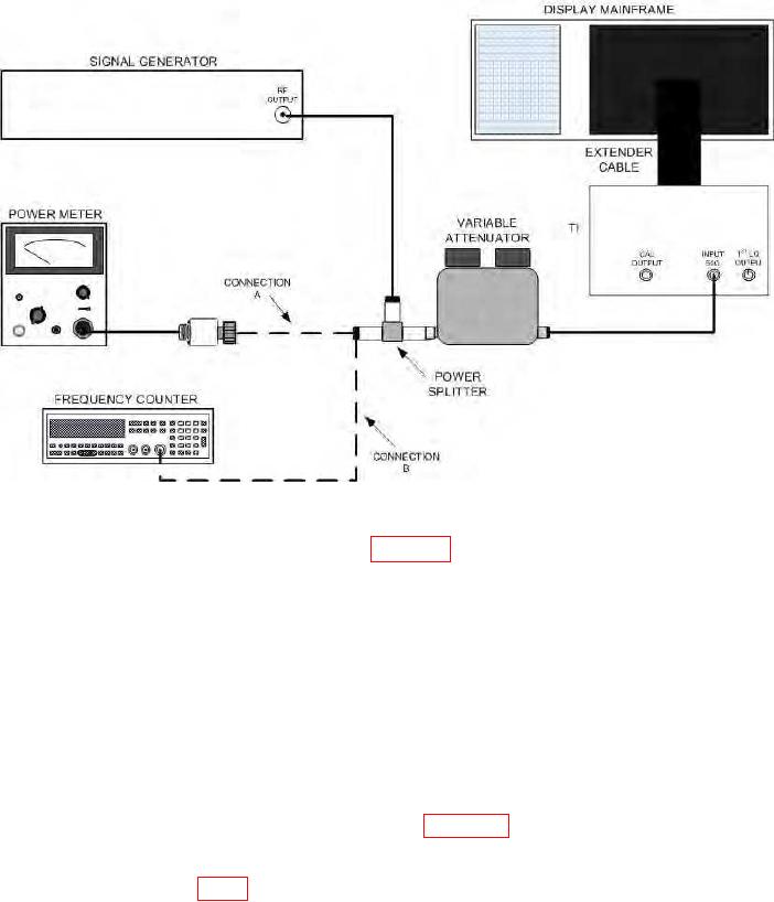
Figure 2. Calibrator levels - equipment setup.
(9) Connect equipment as shown in figure 2 (connection B). If frequency counter
does not indicate between 279.7 and 280.3 MHz (SN 2118A and below, 279.95 and 280.05
MHz), perform b (4) through (6) below.
b. Adjustments
indication on power meter. Record signal position and amplitude on crt.
NOTE
Variable attenuator and power splitter errors must be included
in b (1) above.
(2) Disconnect equipment as shown in figure 2 and connect 280 MHz CAL
OUTPUT to INPUT 50Ω.
(3) Adjust A9R5 (fig. 3) to position signal peak to reference established in (1) above (R).
(4) Connect CAL OUTPUT to INPUT 50Ω.
(5) Center 280 MHz signal on TI display.
9

