
TB 9-6625-2263-24
(5) Set calibrator for a 100 V, 200 Hz output. Adjust AC CONVERTER R433 100 V
200 Hz (fig. 1) for TI indication between 99.994 and 100.006 VAC (R).
(6) Set calibrator for a 100 V, 20 kHz output. Adjust AC CONVERTER R426 100 V
20 kHz (fig. 1) for TI indication between 109.988 and 110.012 VAC (R).
(7) Set calibrator for a 600 V, 200 Hz output. Adjust AC CONVERTER R438 600 V
200 Hz (fig. 1) for TI indication between 599.94 and 600.06 VAC (R).
11. Power Supply
a. Performance Check
NOTE
Do not perform power supply checks if all other parameters are
in tolerance.
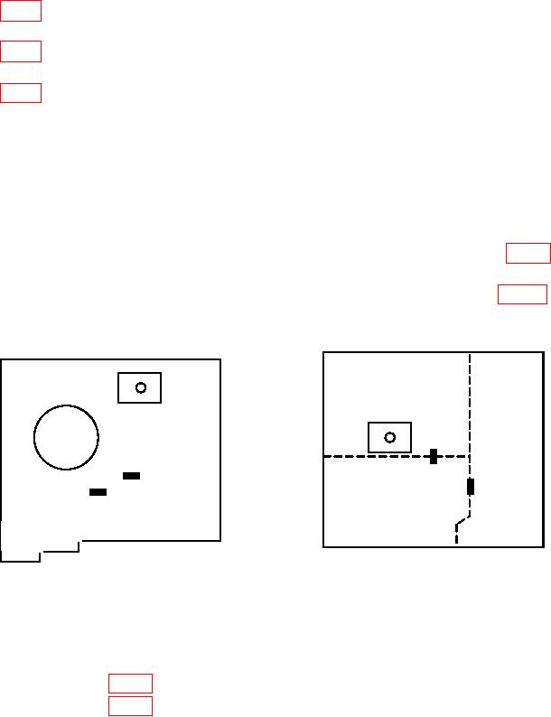
(1) Connect multimeter INPUT HI to TP201 VCC and LO to TP202 VSS (fig. 3). If
multimeter does not indicate between +4.9 and +5.2 V dc, perform b (1) below.
(2) Connect multimeter INPUT HI to TP701 and LO to TP702 (fig. 3).
If
multimeter does not indicate between +4.9 and +5.2 V dc, perform b (2) below.
R204
R710
TP702
TP202
TP701
VSS
TP201
ANALOG CONTROLLER
VCC
POWER SUPPLY
AC
CONVERTER
Figure 3. Power supply - adjustment locations.
b. Adjustments
(1) Adjust R204 (fig. 3) for a multimeter indication between +4.9 and +5.2 V dc (R).
(2) Adjust R710 (fig. 3) for a multimeter indication between +4.9 and +5.2 V dc (R).
12. Final Procedure
a. Deenergize and disconnect all equipment.
b. Annotate and affix DA label/form in accordance with TB 750-25.
11(12 Blank)

