
TB 9-6625-2283-35
(3) Adjust ↑ ↓ POSITION control to set the top of the pulse 1 major division above
the center graticule line.
(4) Set MARKER control to 0 meters.
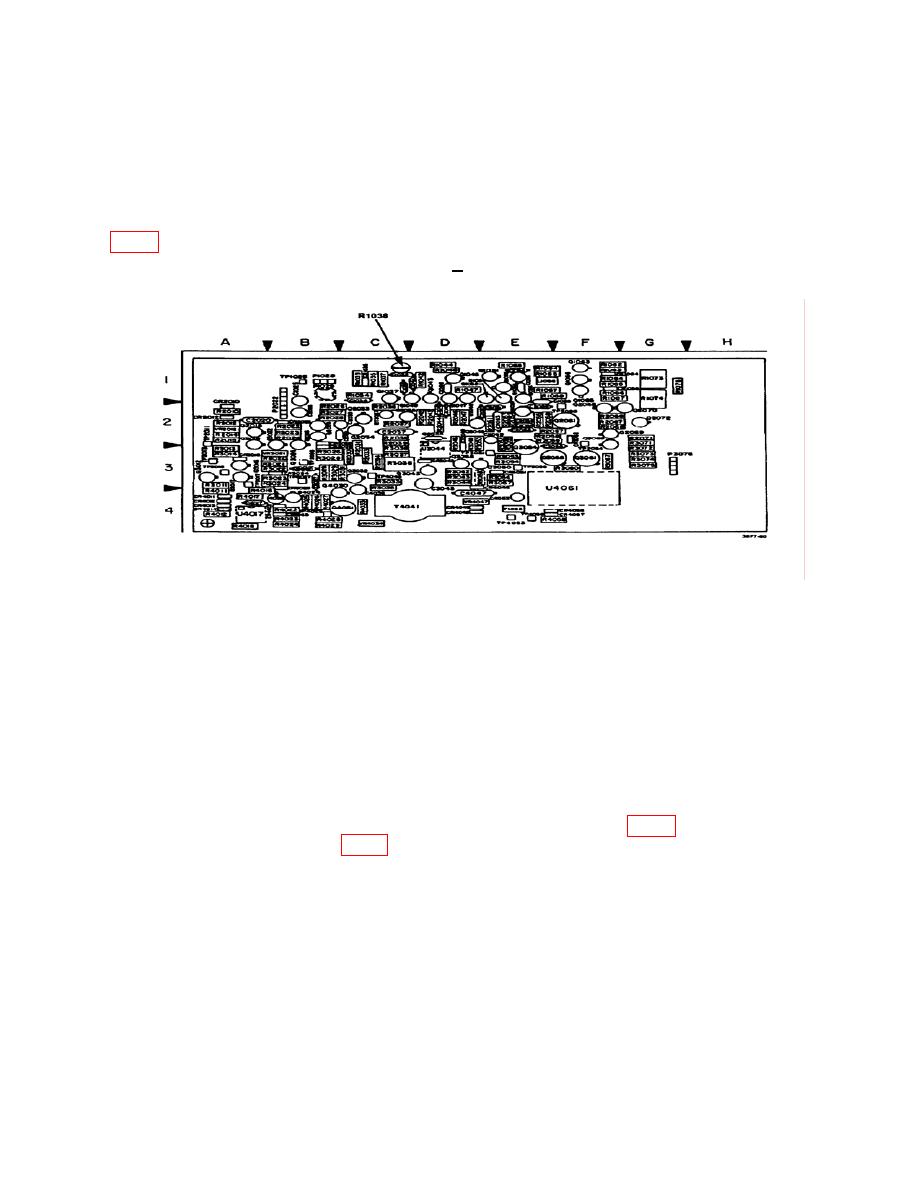
(5) Press and hold SWEEP pushbutton for continuous sweep while adjusting R1038
location of the marker. (Indication will be to +25 feet or less.) (R).
10. Power Supply
NOTE
Do not perform power supply check if all other parameters are
within tolerance.
a. Performance Check
(1) Connect the power supply extender between the supply and the TI. Do not twist
the extender.
(2) Set POWER switch to ON.
(3) Activate the contacts on the power switch (next to the transformer).
(4) Connect frequency counter ground connection to VR1050 (fig. 6) and frequency
counter center lead to TP4031 (fig. 6).
(5) Adjust trigger level of frequency counter for a frequency counter indication of
approximately 50 kHz.
(6) If frequency counter does not indicate between 49500 and 50500 Hz, perform
b (1) below.
PIN: 071379-002

