
TB 9-6625-2323-24
(5) Using measuring receiver and RF power techniques in Log Mode, sweep the TI
from 2 GHz to 18 GHz in 1 GHz steps and record the highest and lowest levels.
(6) Calculate the flatness using the formula below. The flatness will be less than or
equal to the maximum limit listed in table 4.
Flatness = (highest lowest)/ 2
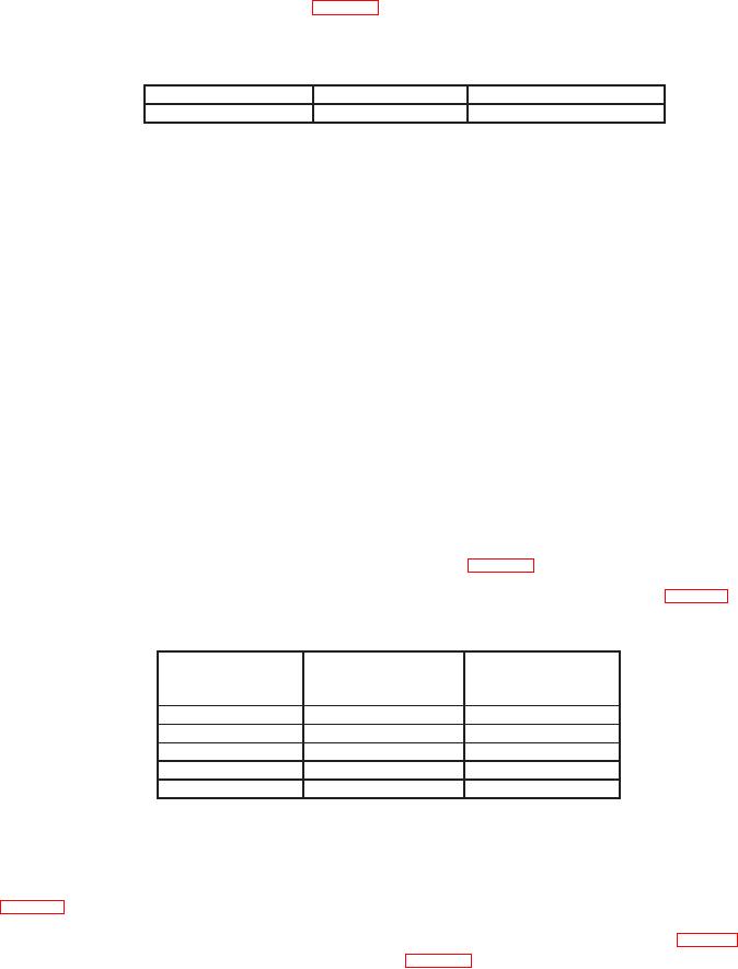
Table 4. Output Level Flatness
Start frequency
Stop frequency
Max limit (dB)
2 GHz
18 GHz
0.799
b. Adjustments. No adjustments can be made.
10. Attenuator Accuracy
a. Performance Check
(1) Connect power sensor module to measuring receiver POWER REF output.
(2) Zero and calibrate the power sensor.
(3) Disconnect the measuring receiver power sensor module from the measuring
receiver POWER REF output and connect it to the TI RF OUTPUT.
(4) Press TI keys as listed in (a) through (e) below:
(a) System, Reset.
(b) Output On Off to off.
(c) Frequency Control, F0, Edit F0, 2, and GHz Sec dBm.
(d) Output On Off to on.
(e) Level Control, L1, Edit L1, 0, and MHz ms dB.
(5) Using measuring receiver and RF power techniques in Log Mode verify that the
measuring receiver indicates within tolerances listed in table 5.
(6) Using technique of (4) (e) set the TI to the remaining levels listed in table 5 and
repeat (5) above.
Table 5. 2 GHz Output Level Test 1 dB Steps
Test instrument
Measuring receiver
Measuring receiver
output level
Min (dB)
Max (dB)
(dB)
0
-1
1
-1
-2
0
1
0
2
2
1
3
3
2
4
(7) Press Level Control, L1, Edit L1, 0, and MHz ms dB.
(8) Using standard tuned level measurement techniques, verify the measuring
receiver indicates within minimum and maximum limits for TI output level as listed in
table 6 below.
(9) Use the TI arrow key to decrement the output level 10 dB, as indicated in table 6,
verifying the indication is within limits listed in table 6.

