
TB 9-6625-2327-24
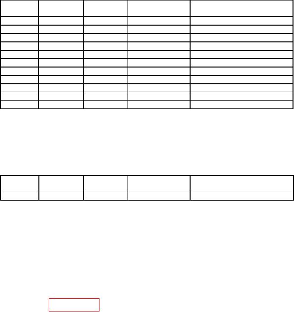
Table 20. Adjustment Setup #104 Through #114.
Nominal rise
Setup #
Amplitude
Typical test requirements
time
104
100 Hz
1 Vp-p
3.2 ns
Fastest transition range 0
105
100 Hz
1 Vp-p
4.5 ns
Mid transition range 0
106
100 Hz
1 Vp-p
64
ns
Slowest transition range 0
107
100 Hz
1 Vp-p
8
ns
Fastest transition range 1
108
100 Hz
1 Vp-p
241
ns
Slowest transition range 1
109
100 Hz
1 Vp-p
161
ns
Fastest transition range 2
110
100 Hz
1 Vp-p
4.9 us
Slowest transition range 2
111
100 Hz
1 Vp-p
2.6 us
Fastest transition range 3
112
100 Hz
1 Vp-p
82
us
Slowest transition range 3
113
100 Hz
1 Vp-p
57
us
Fastest transition range 4
114
100 Hz
1 Vp-p
1.75 ms
Slowest transition range 4
(40) When Setup # 115 is displayed press BEGIN key.
(41) Configure oscilloscope controls to measure duty cycle with a 50 Ω input.
(42) Using numerical keypad, adjust displayed Meas'd Duty Cycle to match
oscilloscope measured duty cycle. Press ENTER VALUE key, when values match.
Table 21. Adjustment Setup #115.
Nominal duty
Setup #
Amplitude
Typical test requirements
cycle
115
25.1 MHz
1 Vp-p
50%
Fastest transition range 0
NOTE
The factory default secure code is AT33250A. If the secure
code has been changed and is now unknown the manufacturer's
manual, section 4, describes how to unsecure the instrument
without a security code.
(43) Enter the secure code using the knob to change the displayed character, and the
arrow keys to move to the next character.
(44) Press Secure and Done key.
(45) Perform paragraphs 8 through 12 to verify alignment was successful.
14. Final Procedure
a. Deenergize and disconnect all equipment.
b. Annotate and affix DA label/form in accordance with TB 750-25.

