
TB 9-6625-2340-24
RES BW, 30, kHz.
(d)
LOG ENTER dB/DIV, 1, dB.
(e)
(4) Press TI MARKER PEAK SEARCH and MARKER
REF LEVEL and
record the displayed marker amplitude in first row (Reference Indication column) of table 10.
(5) Press the TI , and MARKER PEAK SEARCH keys and record displayed
amplitude level in table 10.
(6) Repeat (5) above for remaining log scales and calculate log scale deviation using
the formula below. If calculated deviation is not within limits specified in table 10, perform
b below.
Marker amplitude
reference indication = deviation
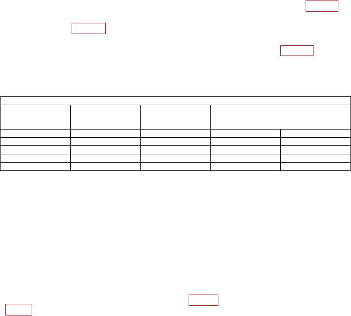
Table 10. Log Scale Deviation
Test Instrument
(Reference
SCALE
MKR amplitude
indication)
Calculated deviation
(dB/div)
(dBm)
(dBm)
(dB)
Min
Max
1
(
)
0 (ref)
0 (ref)
0.5
2
(
)
0.5
0.5
5
(
)
0.5
0.5
10
(
)
0.5
b. Adjustments
(1) Set TI LINE switch to STANDBY.
(2) Remove TI top cover.
(3) Remove cables attached to the A3 digital storage cage.
(4) Remove digital storage cage cover.
(5) Reconnect cables to digital storage cage removed in (3) above.
(6) Connect TI RF INPUT to TI CAL OUTPUT through attenuator No. 2.
(7) Set TI LINE switch to ON.
(8) Press TI 2-22 GHz key.
(9) Connect multimeter HI to A4A1TP1 (fig. 21) and multimeter LO to A3A9TP1

