
TB 9-6625-2349-35
10. Ac Voltage
a. Performance Check
(1) Connect calibrator output to TI + and COM.
(2) Set TI function/range switch to 2.5 ACV.
(3) Set calibrator initial output for 2.5 V at 400 Hz. Adjust calibrator output
controls for a 2.5 V ac indication on TI. Calibrator control Error display will indicate
within +4 percent.
(4) Repeat technique of (2) and (3) above for TI function/range switch and calibrator
initial output settings listed in table 5. Calibrator control Error display will indicate
within +4 percent for each TI indication.
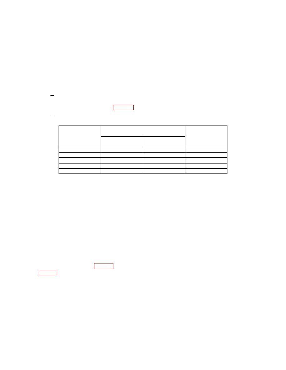
Table 5. Ac Voltage
Test instrument
Calibrator initial
function/range
output settings
Test instrument
switch settings
Voltage
indications
(ACV)
(V)
(Hz)
(V ac)
10
10
400
10
50
50
400
50
250
250
400
250
500
500
400
500
1 k1
1000
400
1000
1Connect
calibrator output to TI AC 1k V and COM.
b. Adjustments. No adjustments can be made.
11. Resistance
a. Performance Check
(1) Disconnect TI inputs.
(2) Set TI function/range switch to OHM x1.
(3) Connect leads to TI + and COM. Short leads together and adjust 0 Ω ADJ
control for 0 indication on Ω scale.
(4) Connect TI + and COM to resistance standard. Adjust resistance standard for a
20 Ω indication on TI. Resistance standard will indicate between 17.74 Ω and 22.55 Ω.
(5) Repeat technique of (1) through (4) above for TI function/range switch settings
and indications listed in table 6. Resistance standard will indicate within limits specified
in table 6.
b. Adjustments. No adjustments can be made.

