
TB 9-6625-2351-35
18. Power Supply
NOTE
Do not perform power supply check if all other parameters are
within tolerance.
a. Performance Check
(1) Press TI LINE switch to OFF.
WARNING
Allow 30 seconds for the high-voltage capacitors to discharge
before removing the protective cover from the A6 power supply
(located at TI top).
(2) Remove A6 power supply cover.
(3) Set multimeter to measure 1000V dc.
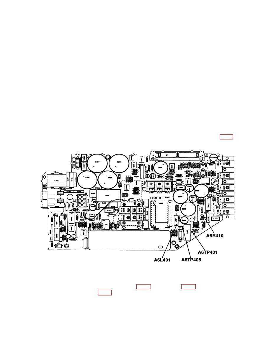
(4) Connect multimeter INPUT HI to A6TP405 (fig.6) and INPUT LO to A6TP401 (fig. 6).
(5) Record dc voltage marked on A6A1 HV module (located at TI top).
(7) and (8) below. If A6L401 (fig. 6) is 20 mH, perform (7) and (9) below.
(7) Press TI LINE switch to ON.

