
TB 9-6625-340-35
(5) Repeat (2) and (3) above.
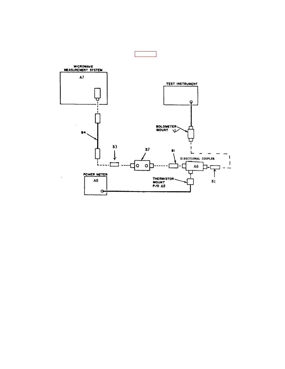
(6) Connect equipment as shown in figure 3.
Figure 3. Power input - equipment setup.
(7) Adjust POWER control to 1.0 on 0 to 1.0 scale.
(8) Adjust microwave measurement system (A7) to upper frequency as indicated on
TI bolometer mount efficiency chart. If chart is not available, adjust to 9.8 GHz.
NOTE
The output coupling factor for directional coupler (A6) must be
considered during the performance of (9) through (23) below.
(9) Adjust microwave measurement system output and variable attenuator (B7)
controls for a null indication on TI NULL INDICATOR meter. If power meter (A8) does
not indicate between .95 and 1.05 mW, perform b(1) and (2) below.
(10) Reduce input level by adjusting variable attenuator controls by 10 dB.
(11) Adjust POWER control to .10 on 0 to 1.0 scale.
7

