
TM 9-4931-294-15/2
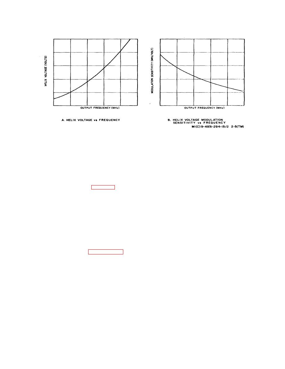
Figure 2-5. Typical Performance Characteristic8 of a BWO Tube.
operating frequency of a BWO increases exponentially
change in MHz per volt change of helix potential
with a linearly increasing helix voltage. Therefore, if the
c. Couplers and Crystal Mixers.
helix voltage is increased in an inversely exponential
manner, the BWO frequency will increase linearly. The
(1) The purpose of the couplers within the rf heads
BWO power supply provides an exponential helix voltage,
is to sample the rf power output of the BWO for
adjustable from + 100 to + 2500 volts. The collector
application to the tunable synchronizer.
potential has a similar characteristic, and is 130 volts
(2) The crystal mixers are used only in the Kand
above the helix voltage. Other voltages provided by the
Aband rf heads (refer to part B of figure 2-2). Since the
BWO power supply include an anode voltage, variable
tunable synchronizer cannot lock on to a frequency above
from 0 to +200 volts, a +6.3volt BWO filament voltage,
18 GHz, the sampled output from the auxiliary arm of the
and a 0 to 6 volts varactor supply. In addition, local power
coupler is fed to the crystal mixer. Although physically
supplies generate internal dc voltages.
located in the rf head, this mixer forms an integral part of
b. Overall Block Diagram Discussion.
the tunable synchronizer. A suitable harmonic signal from
the tunable synchronizer is also applied to the mixer,
(1) Primary power is applied through AC POWER
resulting in an IF signal of approximately 25 MHz which is
switch S101 (figure 26) which, when closed, allows ac to
then reapplied to the tunable synchronizer.
excite transformer T701. Secondary windings of T701
feed the regulated filament supply, the regulated +22.5volt
local supply, and the unregulated 40volt supply. The
24. BWO Power Supply
filament supply directly feeds regulated +6.3 volts to the
BWO tube, however application of 40 volts to the helix
a. General.
As discussed in paragraph 2-7 b, the
supply and
2-7

