
TM 9-4935-294-15/2
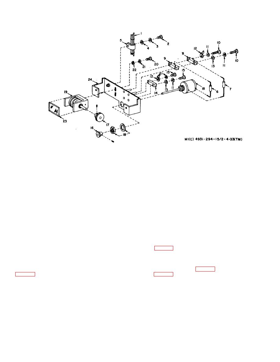
1--Harnes-792308-1
12-Lug, solder-7923256-1
2-Screw, machine, pan hd, no. 6 32, 1/2 in. ig, UNC-
13--Washer, fiat, round, steel, cd-MS27183-2
2A-MS35206-230
14-Resistor variable (R156065)-792302-3
3-Washer, lock, split, helical, no. 6-MS35338-41
15-Screw, machine, pan hd, no. 2-56, 5/8 in. Ig,
4-Washer, flat-MS27183-5
UNC-2A-MS35206-208
5-Clamp, loop-plastic, wire support--MS25281-5
16-Gear, helical-792308-16
6-Resistor, fixed (R1506)-RH20-X1501F
17-Gear, helical-79230588
7-Resistor, fixed (R1508)-RH20-X6621F
18-Resistor, variable, 10-turn (R-1502)--7923070
8-Resistor, variable (R15Ol)-79280724
19-Counter assy-7923057
9--Resistor variable (R1503)-7923072-1
20-Screw, machine, pan hd, no. 4-40, 3/8 in. Ig,
10-Screw machine, pan hd, no. 2-56, 7/8 in. lg,
UNC-2A-MS35206-215
UNC-2A-MS-85206-210
21-Washer, lock, split, helical, no. 2-MS3538-40
11-Washer, lock, split, helical, no. 2-MS35338-39
22-Washer, flat, round, steel, cd-MS27183-3
23-Window-7923060
24-Bracket assy-7923041-1
Figure 4-33. Counter Assembly 7923056-8, Exploded View.
(9) Apply sealing compound10528558 to BWO
(3, fig. 4-31) on rf head chassis (41) with two screws (4)
tube (5) bracket mounting screws (4), then tighten.
and secure.
Check position, routing and condition of harness.
(12) Connect and solder the green, orange, and
(10) Connect and solder the red harness lead to
blue harness leads to connector bracket assembly (3)
terminal 2 on dispersion PC board assembly (refer to 1,
solder lug (refer to 17, fig. 4-12). (13) Install side cover
(1, fig. 4-31) with 10 screws (2).
c. Disassembly of A-Band Rf Head. To disas-
(11)
Install
connector
bracket
assembly
Change 1 4-53

